Tomographic phase microscopy

a phase microscopy and tomographic technology, applied in the field of tomographic phase microscopy, can solve the problems of inability to measure three-dimensional spatial variation, cumbersome procedures, and limited high-resolution light microscopy,

Active Publication Date: 2009-05-14
MASSACHUSETTS INST OF TECH
View PDF4 Cites 217 Cited by
  • Summary
  • Abstract
  • Description
  • Claims
  • Application Information

AI Technical Summary

Benefits of technology

[0029]FIGS. 13A-13D illustrate the effect of sampling depth on refractive index tomograms; FIG. 13A shows a phase image of a 10 μm polystyrene bead with the focus 4 μm above the center of the bead; FIG. 13B shows a quantitative phase image after applying the propagation correction, with the focus brought to the center of the bead and the color bar indicates phase in radians; FIG. 13C is an x-y slice of the refractive index tomogram for the focus the same as in 13A; FIG. 13D is an x-y slice of the refractive index tomogram after applying the propagation algorithm. The color bar indicates the refractive index measured at λ=633 nm.

Problems solved by technology

High resolution light microscopy is limited not only by the diffraction properties of light but also the optical inhomogeneities of the sample.
This procedure is cumbersome and is limited by the tendency of some cells to be altered by the immersion liquids, which are typically not physiologically controlled.
More recently, accurate measurements of average index have been performed using quantitative phase microscopy techniques, but measurement of three-dimensional spatial variation has not been possible.

Method used


Image

  • Tomographic phase microscopy
  • Tomographic phase microscopy
  • Tomographic phase microscopy

Examples


Embodiment Construction

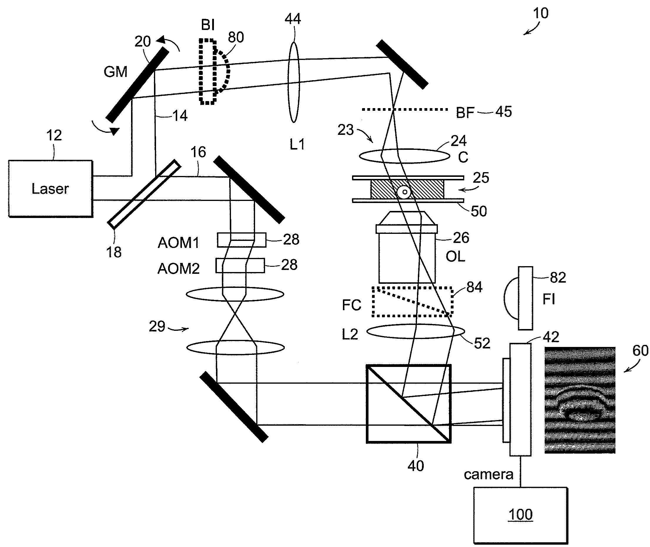
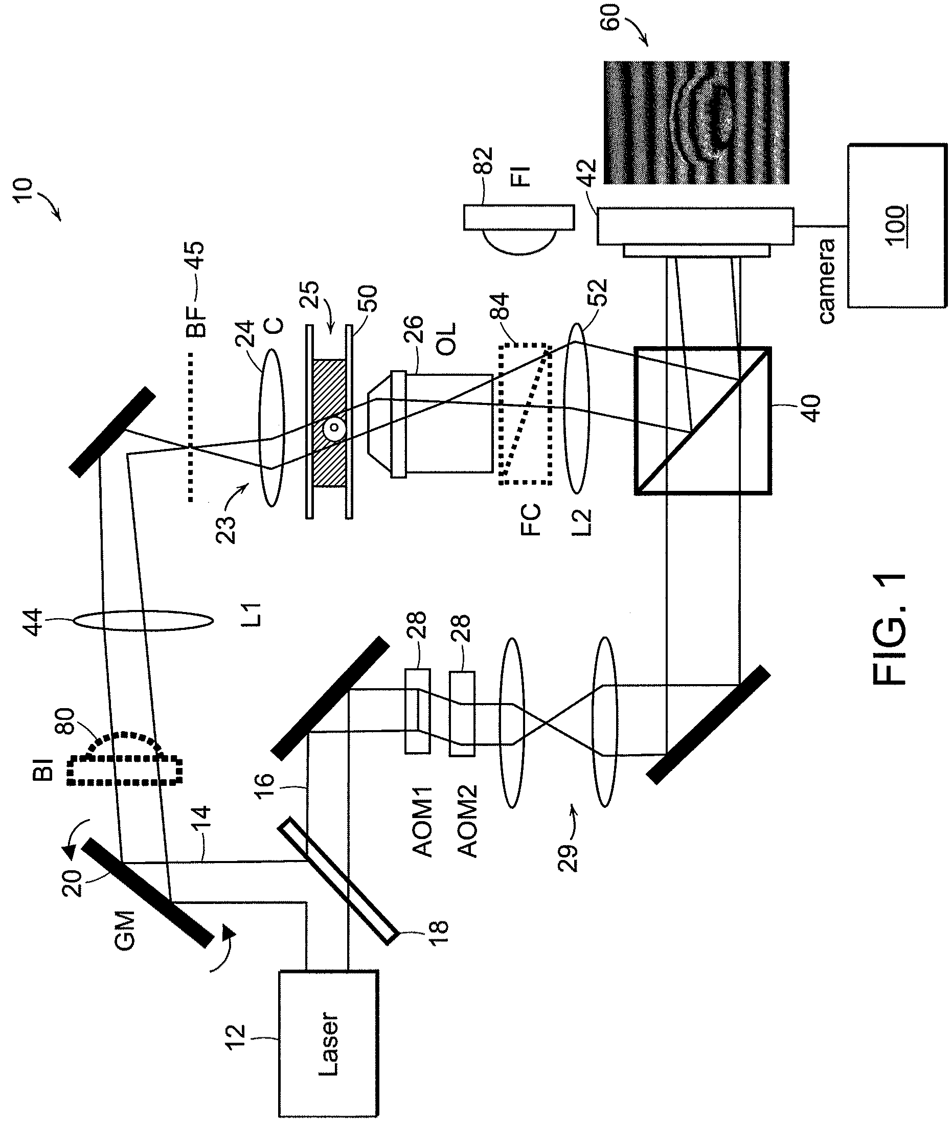
[0037]The system 10 for performing measurements is illustrated in FIG. 1 and is based on a Mach-Zehnder heterodyne interferometer, which provides quantitative phase images from time-dependent interference patterns induced by the frequency shifting of a reference beam relative to the sample beam. A light source 12 such as a helium-neon laser beam (λ=633 nm) is divided into measurement 14 and reference arm 16 paths by a beamsplitter 18. An actuator 20, such as a galvanometer-mounted tilting mirror, is used to vary the angle of illumination 23 of the medium 25 being measured, which is positioned between the oil-immersion condenser 24 and objective lenses 26. In the reference arm, the laser beam passes through two acousto-optic modulators 28 (AOMs) which shift the frequency of the laser beam by 1250 Hz. A beamsplitter 40 recombines the sample and reference laser beams, forming an interference pattern 60 at the image plane. For each angle of illumination a detector 42 such as a CMOS came...


PUM

PropertyMeasurementUnit
plurality of anglesaaaaaaaaaa
refractive indexaaaaaaaaaa
diameteraaaaaaaaaa

Abstract

The present invention relates to systems and methods for quantitative three-dimensional mapping of refractive index in living or non-living cells, tissues, or organisms using a phase-shifting laser interferometric microscope with variable illumination angle. A preferred embodiment provides tomographic imaging of cells and multicellular organisms, and time-dependent changes in cell structure and the quantitative characterization of specimen-induced aberrations in high-resolution microscopy with multiple applications in tissue light scattering.

Description

CROSS REFERENCE TO RELATED APPLICATIONS[0001]This application claims the priority of U.S. Provisional Application No. 60 / 958,997 filed Jul. 10, 2007 entitled, TOMOGRAPHIC PHASE MICROSCOPY; and to U.S. Provisional Application No. 60 / 964,250, filed Aug. 10, 2007, entitled TOMOGRAPHIC PHASE MICROSCOPY; and to the U.S. Provisional Application No. 61 / 132,670 filed Jun. 20, 2008, entitled TOMOGRAPHIC PHASE MICROSCOPY. The whole of each of the aforementioned provisional applications is incorporated by reference herein.STATEMENT REGARDING FEDERALLY SPONSORED RESEARCH[0002]The invention was made with support from National Science Foundation Grant DBI-0754339 and National Institutes of Health Grant P41-RR02594-18. The United States Government has certain rights in the invention.BACKGROUND OF THE INVENTION[0003]High resolution light microscopy is limited not only by the diffraction properties of light but also the optical inhomogeneities of the sample. Adaptive optics and deconvolution techniq...

Claims


Application Information

Patent Timeline
Patent Type & Authority Applications(United States)
IPC IPC(8): G01N33/48G01N21/41
CPCG01N21/45G01N21/6458G01N21/51G03H1/0443G03H1/265G03H2001/0458G01N21/6486G01N2021/458G01N2201/061G01N2201/105G01N2201/12
Inventor CHOI, WONSHIKDASARI, RAMACHANDRA RAOFANG-YEN, CHRISTOPHER M.FELD, MICHAEL S.
Owner MASSACHUSETTS INST OF TECH
Why Eureka
Try Eureka