Motor built-in magnetic bearing device

a magnetic bearing and motor technology, applied in the direction of positive displacement liquid engine, piston pump, light application, etc., can solve the problems of reducing the reliability of the air cycle refrigerating turbine unit, reducing the long term durability and lifetime of the bearing unit used to support the main shaft, and reducing the reliability of the turbine unit. , to achieve the effect of increasing the lifetime and long term durability of each of the bearing units and improving the reliability of the turbine uni

Inactive Publication Date: 2009-05-21
NTN CORP
View PDF3 Cites 30 Cited by
  • Summary
  • Abstract
  • Description
  • Claims
  • Application Information

AI Technical Summary

Benefits of technology

[0035]Where the compression expansion turbine system to which the motor built-in magnetic bearing device is applied is applied to the air cycle refrigerating system, since in the compression expansion turbine system, a stabilized high speed revolution of the main shaft can be obtained while the proper clearances of the rotors are maintained, and the long term durability and the lifetime of each of the bearing units can be increased, the reliability of the turbine unit as a whole and, hence, that of the air cycle refrigerating system as a whole can be increased. Since the stabilized high speed revolution, the long term durability and the reliability of the main shaft bearing units of the turbine unit, which has hitherto been posed a major bottleneck to the air cycle refrigerating system, can be increased, the air cycle refrigerating system has now come to be employed practically.

Problems solved by technology

Change in clearance constitutes a cause of an unstable operation during high speed rotation and, therefore, the efficiency tends to be lowered.
For this reason, the thrust load such as described above tends to bring about a reduction in long term durability and lifetime of the bearing unit used to support the main shaft and, in turn, a reduction in reliability of the air cycle refrigerating turbine unit.
Unless the problem associated with the reduction in the long-term durability of the bearing unit is resolved, the air cycle refrigerating turbine unit can be hardly placed in practical use.
However, the technology disclosed in the Japanese Patent No. 2623202 has not yet resolved the problem associated with the reduction in long-term durability of the bearing unit relative to the loading of the thrust load under such a high speed revolution.
For this reason, the presence of a factor or the like that render the control of the thrust bearing unit to be unstable makes it difficult to achieve a stabilized high speed revolution while the minute clearance is maintained between the rotor and the diffuser.
The magnetic bearing unit involves a problem associated with a contact between the rotor and the diffuser at the time of failure of the electric power supply.
It has, however, been found that the motor incorporated magnetic bearing device of the structure described above involves such a possibility that when the motor 68 operates in a high load region and an excessive axial load acts then, the control system for the magnetic bearing units 55 and 56 will become unstable.
In order to alleviate such a condition, the controller 59 is required to be provided with a phase compensating circuit or the like, resulting in complication in structure of the controller 59.

Method used


Image

  • Motor built-in magnetic bearing device
  • Motor built-in magnetic bearing device
  • Motor built-in magnetic bearing device

Examples


third embodiment

[0079]The motor stator 28b of the motor 28 is of a structure, in which a pair of stator yokes 28ba made of a ferromagnetic material and arranged in the spindle housing 14 are provided with respective coils 28bb in a fashion without any core. This motor 28 rotates the main shaft 13 by means of a Lorentz force developed between the motor rotors 28a and the motor stators 28b. Thus, since the motor 28 of the axial gap type in this third embodiment is employed in the form of a coreless motor, the negative stiffness brought about by a magnetic coupling between the motor rotors 28a and the motor stators 28b is zero.

[0080]In other words, in this motor built-in magnetic bearing device, since the motor 28 of the axial gap type is employed in the form of a coreless motor, it is possible to render the negative stiffness, which acts on the motor 28, to be zero and, even in a condition in which a high load acts on the motor 28, the relation in magnitude as expressed by the formula (2) discussed h...

first embodiment

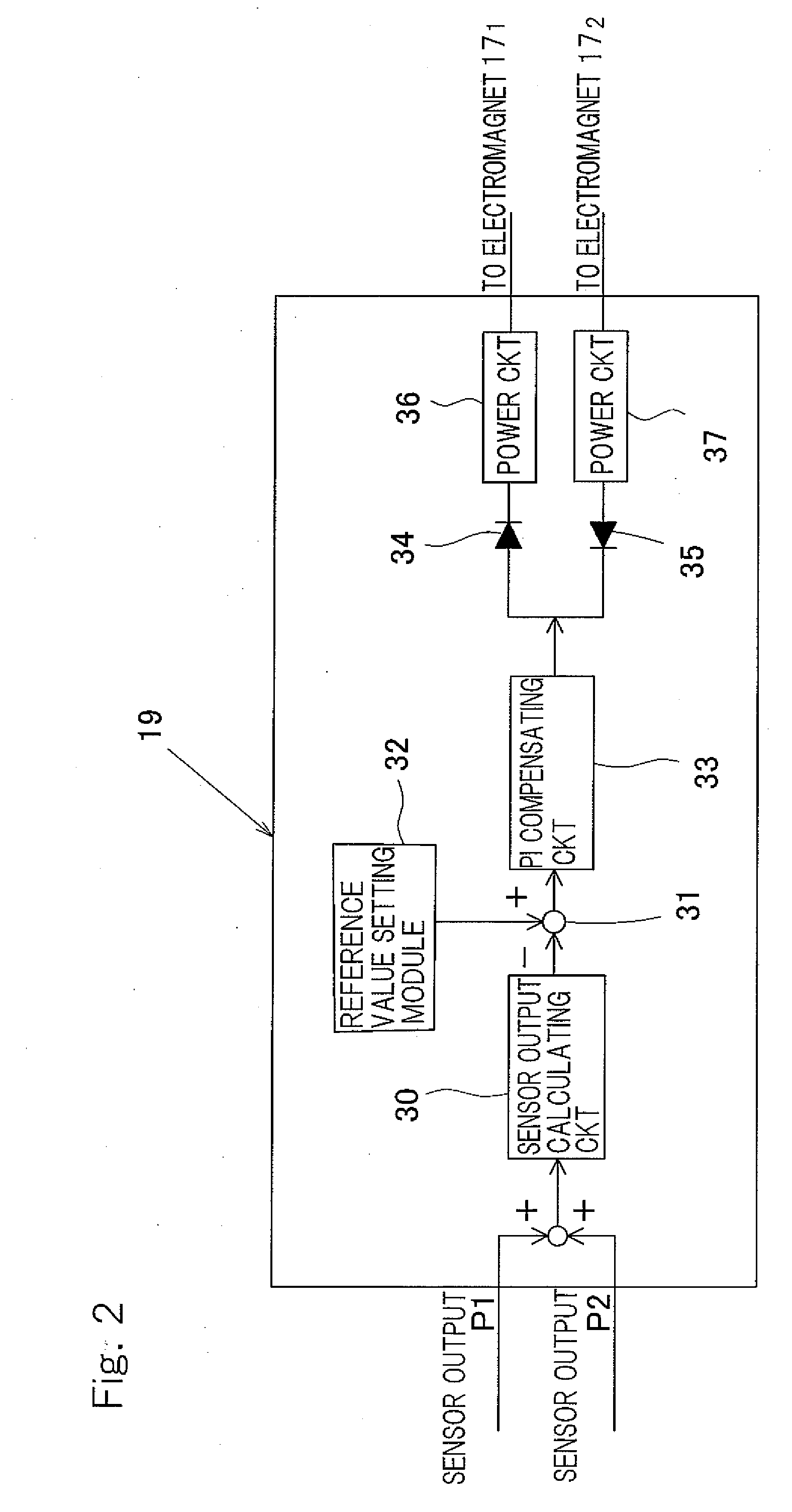
[0081]As a result, in the control region, it is possible to avoid the phase of the mechanical system from being retarded 180° and, accordingly, even when the maximum load acts, the target to be controlled by the controller 19 can be stabilized and controller 19 can have a simplified circuit configuration utilizing a proportion or proportion plus integration as shown in FIG. 2 in connection with the

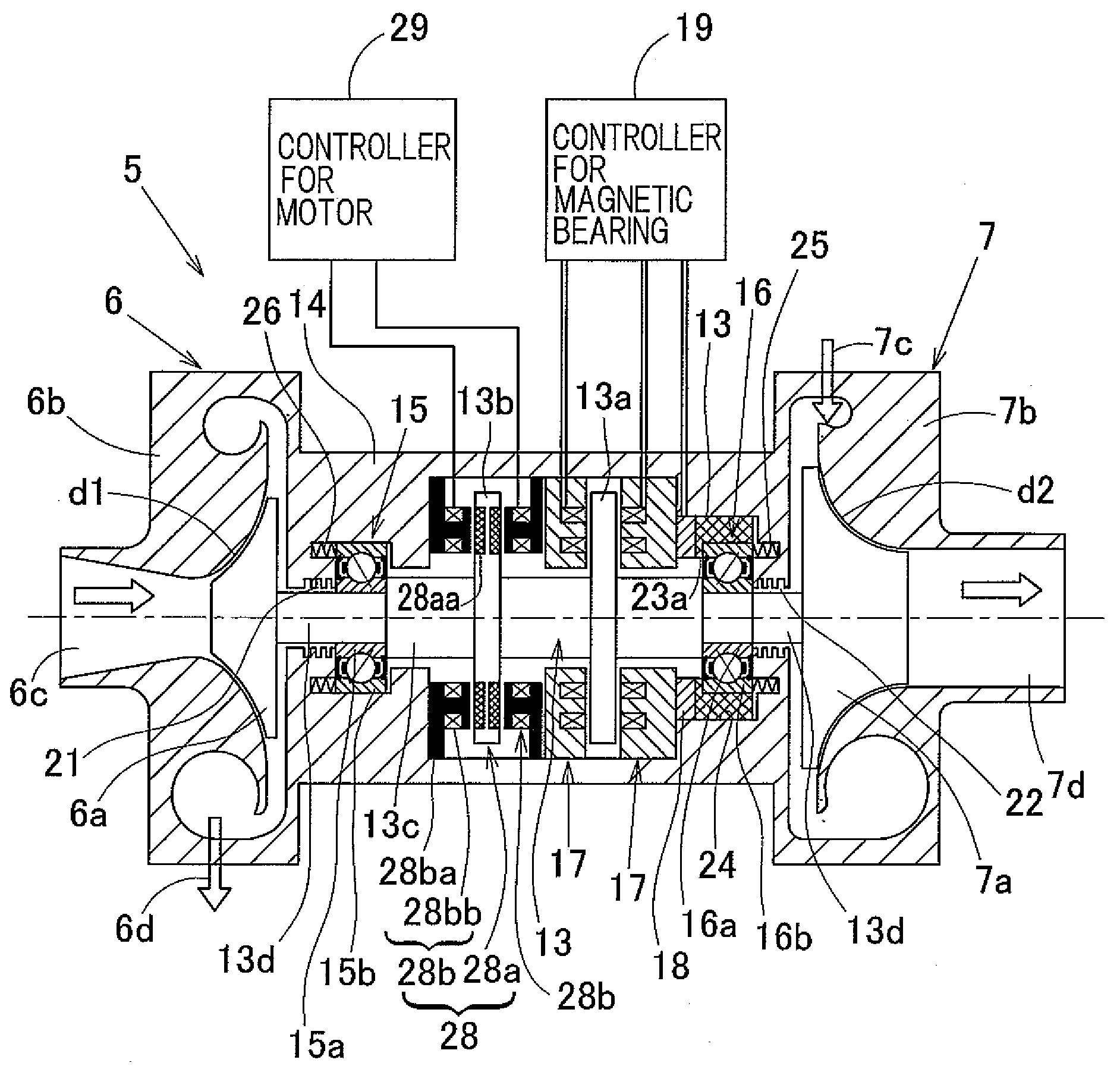
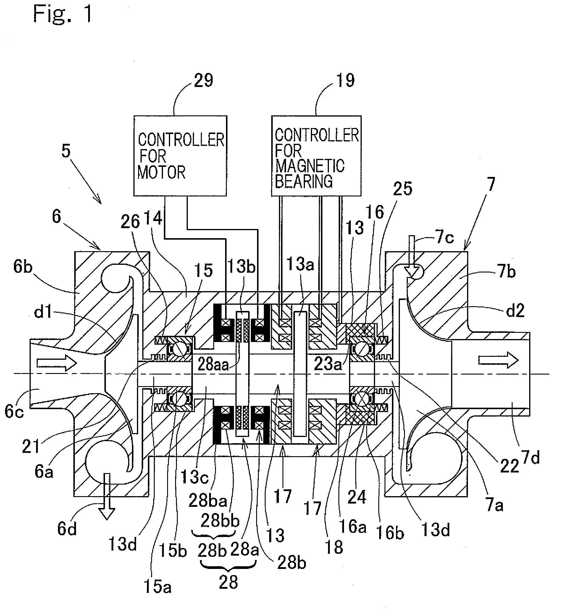
[0082]In the next place, a fourth preferred embodiment of the present invention will be described with particular reference to FIG. 5. FIG. 5 illustrates a longitudinal sectional view of the turbine unit 5 incorporating therein the motor built-in magnetic bearing device according to this embodiment. In this embodiment, component parts shown in and described in connection with this embodiment, which are similar to those shown in and described in connection with the first embodiment, are designated by like reference numerals employed in connection with the first embodiment and, therefore, th...


PUM


Abstract

The device includes a rolling bearing unit supporting a radial load and a magnetic bearing unit supporting an axial load and/or a bearing preload; an electromagnet fitted to a spindle housing so as to confront, on a non-contact basis, a flange shaped thrust plate mounted on a main shaft; a motor rotor of a motor for driving the shaft, and a motor stator opposed to the rotor, the shaft being driven by magnetic or Lorentz forces developed between the rotor and the stator; and a sensor detecting an axial force acting on the bearing unit, and a controller controlling the electromagnet. In this device, the stiffness of a composite spring formed by the bearing unit and a support system for the bearing unit is chosen to be higher than the negative stiffness of a composite spring of a motor part comprised of the electromagnet and the motor.

Description

BACKGROUND OF INVENTION[0001]1. Field of the Invention[0002]The present invention relates to a magnetic bearing device for use in, for example, a turbine unit employed in an air cycle refrigerating system and, in particular, to a motor built-in magnetic bearing device, in which a rolling bearing unit and a magnetic bearing unit are used in combination with each other used, with the magnetic bearing unit supporting one or both of an axial load and a bearing preload.[0003]2. Description of the Prior Art[0004]The air cycle refrigerating system makes use of an air as a coolant and does therefore fail to exhibit a sufficient energy efficiency as compared with the refrigerating system using chlorofluorocarbon or ammonium, but is considered agreeable in terms of environmental protection. In a facility such as, for example, a cold storage warehouse into which a refrigerating air can be directly blown, the total cost can be lowered if a cooling fan device and / or defroster are dispensed with,...

Claims


Application Information

Patent Timeline
Patent Type & Authority Applications(United States)
IPC IPC(8): H02K7/09F04B47/08
CPCF01D15/005F04D25/024F04D29/051F04D29/058F16C19/54F16C25/08F16C39/06F25B9/004H02K5/1732H02K7/083H02K7/09H02K7/14H02K11/001F05D2240/51F05D2240/515F16C2362/52F01D15/10F04D25/0653F16C19/543F16C2380/26H02K11/20
Inventor OZAKI, TAKAYOSHIOKADA, KOICHIYAMADA, HIROYUKISUZUKI, KENICHI
Owner NTN CORP
Why Eureka
Try Eureka