

Apparatus for Integrated Heavy Oil Upgrading
- Summary
- Abstract
- Description
- Claims
- Application Information
AI Technical Summary
Benefits of technology
Problems solved by technology
Method used
Image

Examples
Embodiment Construction
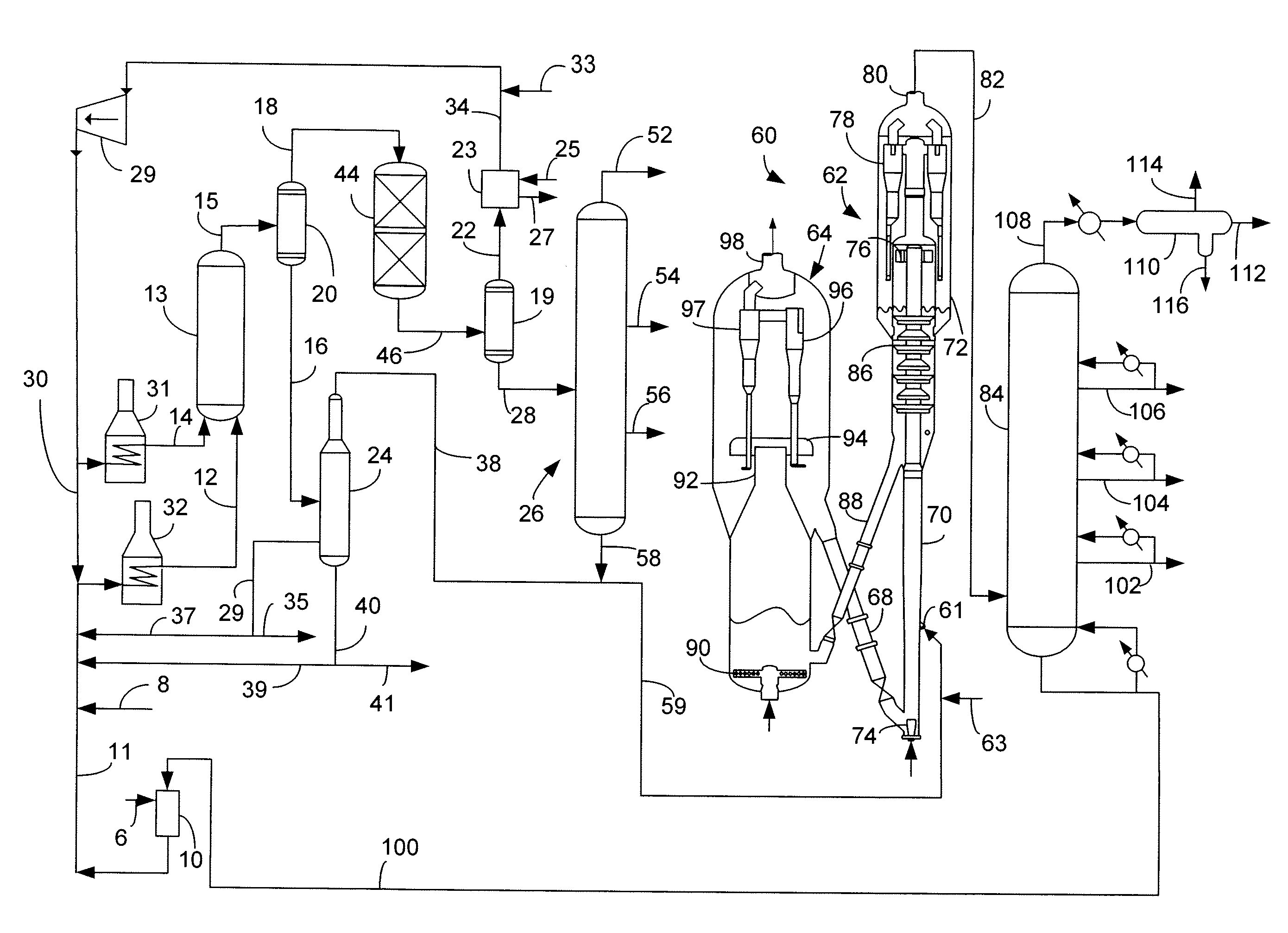
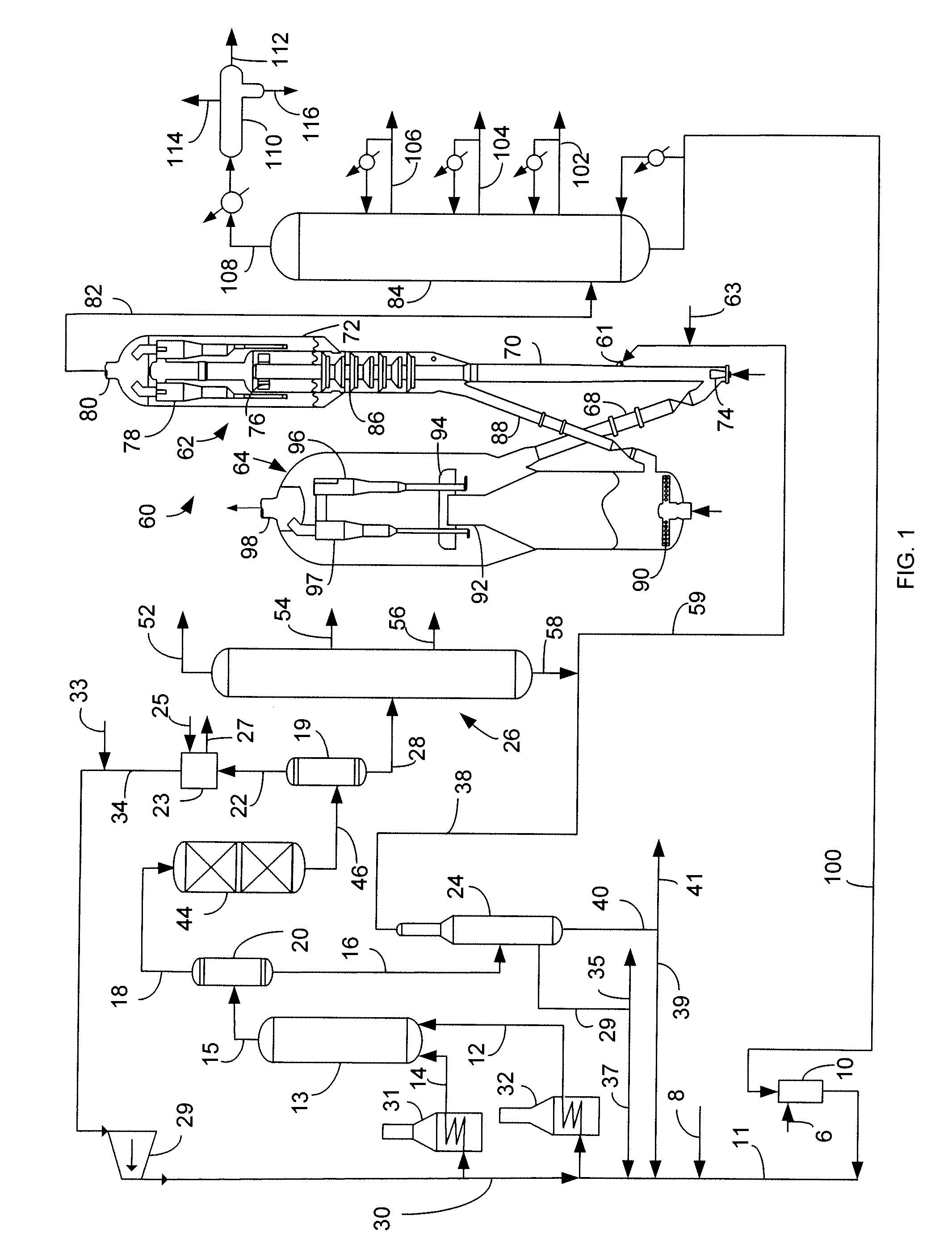
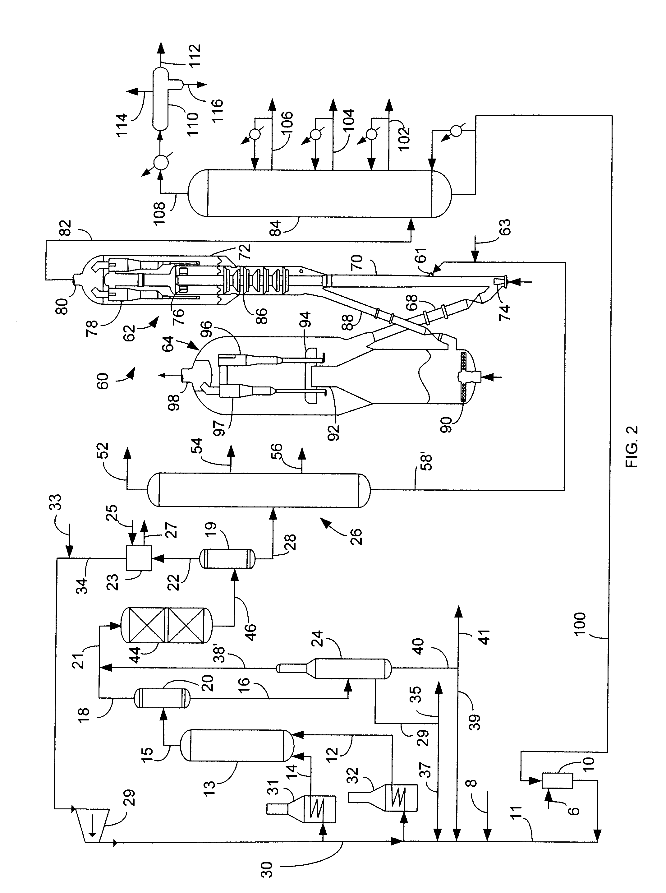
[0013]The apparatus of this invention is capable of processing a wide range of heavy hydrocarbon feedstocks. It can process aromatic feedstocks, as well as feedstocks which have traditionally been very difficult to hydroprocess, e.g. vacuum bottoms, visbroken vacuum residue, deasphalted bottom materials, off-specification asphalt, sediment from the bottom of oil storage tanks, etc. Suitable feeds include atmospheric residue boiling at about 650° F. (343° C.), heavy vacuum gas oil (VGO) and vacuum residue boiling at about 800° F. (426° C.) and vacuum residue boiling above about 950° F. (510° C.). Throughout this specification, the boiling temperatures are understood to be the atmospheric equivalent boiling point (AEBP) as calculated from the observed boiling temperature and the distillation pressure, for example using the equations furnished in ASTM method D1160. Furthermore, the term “pitch” is understood to refer vacuum residue, or material having an AEBP of greater than about 975°...
PUM
 Abstract
Description
Claims
Application Information