Method of injecting dopant gas

a technology of dopant gas and injection method, which is applied in the direction of crystal growth process, polycrystalline material growth, chemistry apparatus and processes, etc., can solve the problem of slow speed at which dopant diffuses all over the semiconductor melt, and achieve the effect of sufficient diffusion of dopant gas

Inactive Publication Date: 2009-06-11
SUMCO TECHXIV
View PDF3 Cites 6 Cited by
  • Summary
  • Abstract
  • Description
  • Claims
  • Application Information

AI Technical Summary

Benefits of technology

[0022]Accordingly, by setting the change rate in a range of 1 rpm/min to 10 rpm/min, the convection currents can be sufficiently caused in

Problems solved by technology

However, although the dopant gas can be injected into the semiconductor melt by the methods of injecting volatile dopant according to Patent Documents 1 and 2, the speed at which the dopant diffuse

Method used


Image

  • Method of injecting dopant gas
  • Method of injecting dopant gas
  • Method of injecting dopant gas

Examples


examples

[0089]Next, examples of the present invention will be described. However, the present invention is not limited to the examples.

[1] Comparison Between Blowing Arrangements

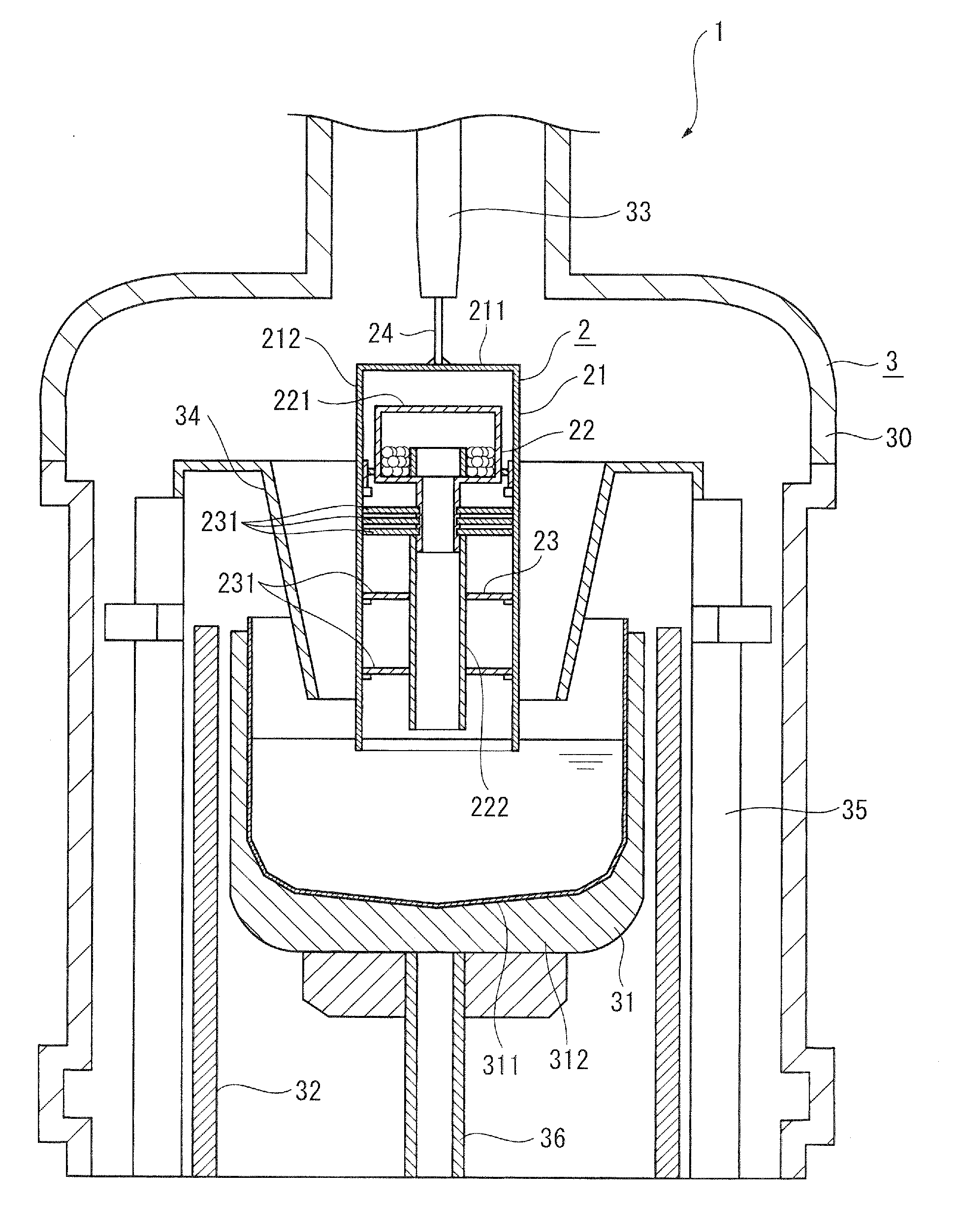
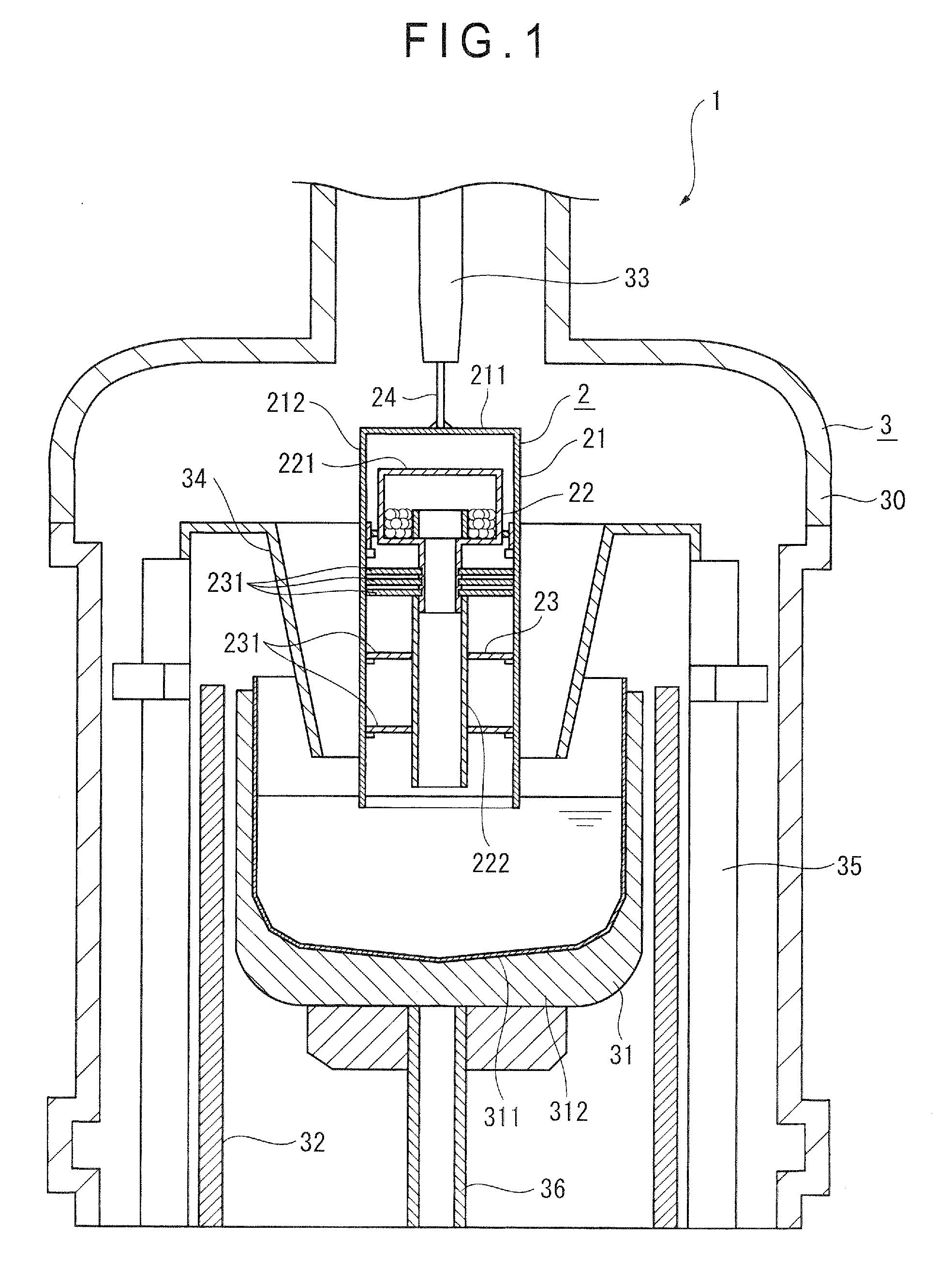
[0090]Comparison was made between: an arrangement where the crucible 31 was rotated alternately clockwise and counterclockwise with the rotary speed thereof being changed while the lower distal end of the lateral portion 212 of the outer tube 21 of the doping device 2 was not soaked in the melt in the crucible 31 as shown in FIG. 3 (Example 1); and an arrangement where the crucible 31 was rotated at a constant speed as in a usual doping (Comparative 1). Evaluation was made based on a dopant-absorption index of Example 1, which is calculated with an absorptivity of Comparative 1 being 100 (absorptivity of Example 1 / absorptivity of Comparative 1×100).

[0091]Doping of both the arrangements was conducted under gas conditions of furnace pressure being 59985 Pa and argon gas flow rate being 200 litters / min.

[0092]Doping con...


PUM


Abstract

According to an dopant-injection method for injecting volatilized dopant gas into semiconductor melt in a crucible (31), the crucible (31) is rotated alternately clockwise and counterclockwise around a support shaft (36) extending in a flowing direction of the dopant gas, so that the dopant gas is blown against the semiconductor melt white the crucible is rotated. Rotating the crucible (31) causes convection currents in the semiconductor melt therein, thereby facilitating diffusion of the blown dopant in the semiconductor melt.

Description

TECHNICAL FIELD[0001]The present invention relates to a dopant-injecting method for injecting volatilized dopant gas into semiconductor melt in a crucible.BACKGROUND ART[0002]In order to adjust resistance value of semiconductor wafers, dopant such as phosphorus or arsenic has been conventionally doped therewith before pulling up ingots during a growing process of silicon monocrystal. Doping is conducted by injecting dopant into semiconductor melt in crucibles.[0003]As the dopant, volatile dopant and nonvolatile dopant are known. When injecting volatile dopant such as arsenic or red phosphorus, the volatile dopant is accommodated in a doping device that includes a container whose lower end is provided with a conduit for guiding gas. The volatile dopant therein is gasified by moving the lower end of the container closer to a surface of the semiconductor melt, such that dopant gas is injected into the semiconductor melt through the conduit. In addition, according to a traditional techn...

Claims


Application Information

Patent Timeline
IPC IPC(8): C30B9/00
CPCC30B15/04C30B35/00C30B29/06
Inventor NARUSHIMA, YASUHITOOGAWA, FUKUOKAWAZOE, SHINICHIKUBOTA, TOSHIMICHI
Owner SUMCO TECHXIV
Why Eureka
Try Eureka