System and apparatus for dermatological treatment

a dermatological treatment and system technology, applied in the field of methods and equipment, can solve the problems of local heating, many safety issues, and energy sources such as lasers or electronic flashlamps, and achieve the effects of facilitating optical radiation, reducing the amount of infrared radiation, and preventing other portions of the tissue from being exposed

Active Publication Date: 2009-06-11
THE GENERAL HOSPITAL CORP
View PDF16 Cites 17 Cited by
  • Summary
  • Abstract
  • Description
  • Claims
  • Application Information

AI Technical Summary

Benefits of technology

[0013]It is one of the objects of the present invention to provide systems and apparatus which facilitate a safe and economical treatment to improve dermatological defects and other therapies involving application of optical radiation to skin tissue. Another object of the present invention is to provide systems and apparatus which can be used for a range of such therapies, such that a single practitioner may treat a variety of dermatological conditions without requiring a significant financial investment in equipment (e.g., energy sources, handpieces, etc.) and / or significant storage space to house such equipment. It is a further object to provide such exemplary systems and apparatus for treating dermatological conditions which may be safe enough to be used at home by a consumer.
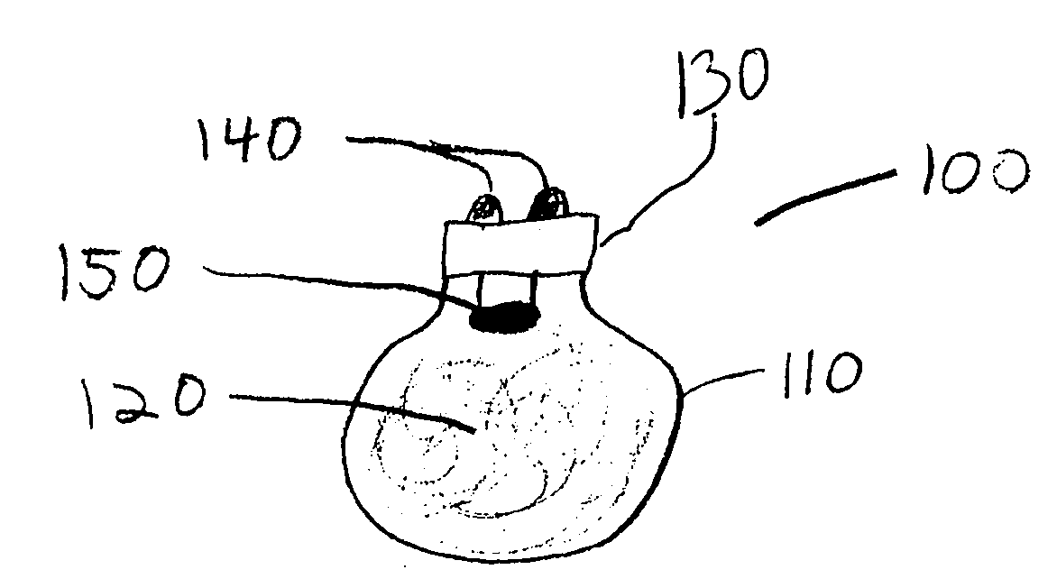
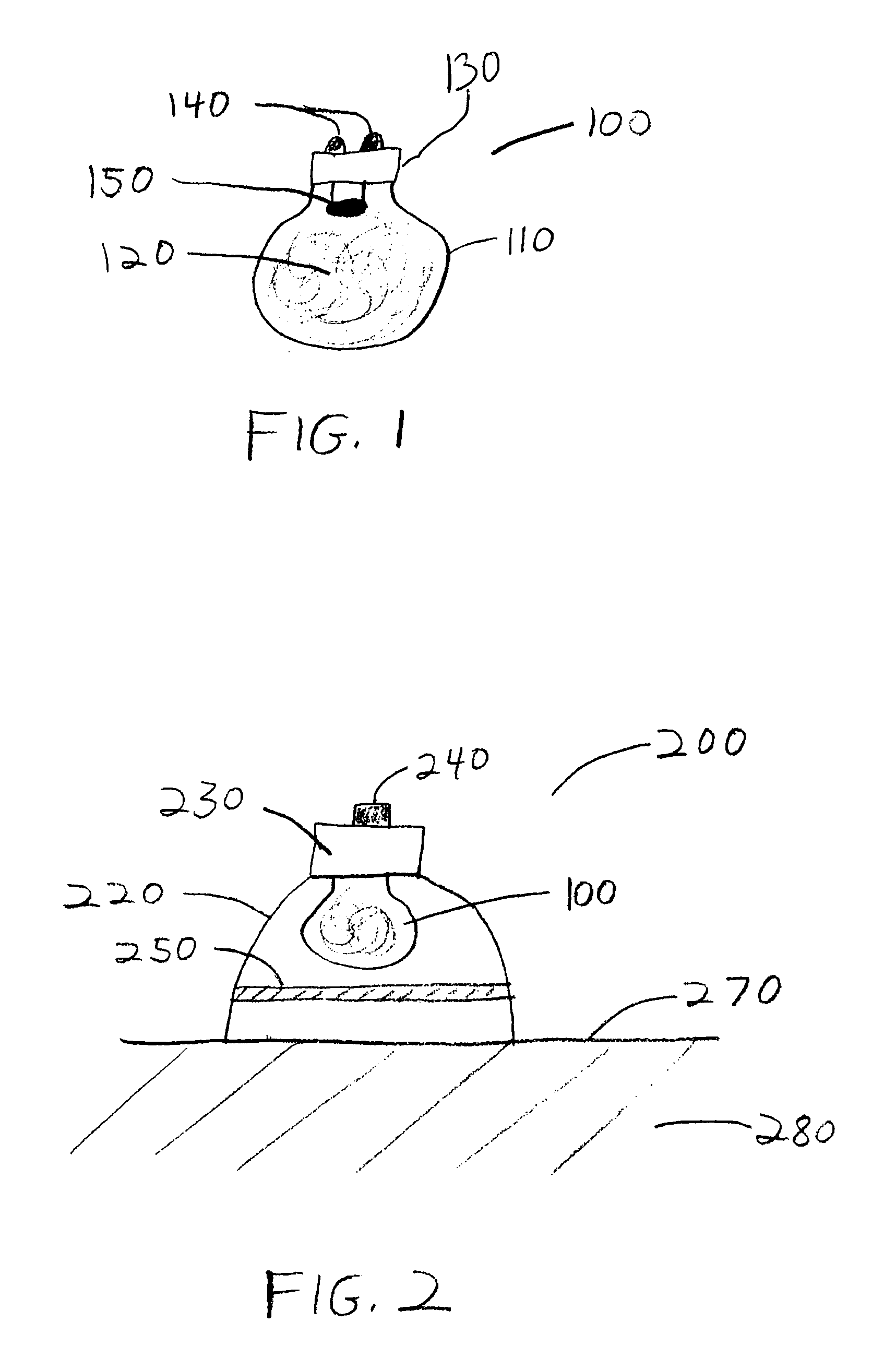
[0015]The combustible material can be a metal or metal alloy, e.g., aluminum, hydronalium, an aluminum alloy, zirconium, magnesium, or another metal, or a combination of a metal with another substance. The combustible material can be provided in a form of a thin filament or foil to allow rapid reaction, e.g., combustion, of the material. Such rapid reaction can produce a pulse of radiation having a high intensity and a short duration, e.g., on the order of tens of milliseconds or less. A particular atmosphere can be provided within the enclosure to enable or enhance the reaction or combustion. Such atmosphere can include, for example, between about 40% and about 100% moisture-free oxygen, or between about 80% and about 100% moisture-free oxygen.
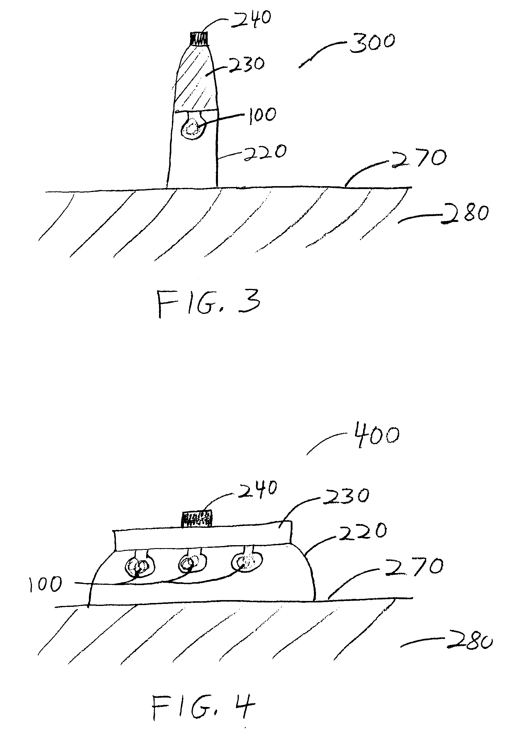
[0023]In certain exemplary embodiments, a water filter may be provided to reduce the amount of infrared radiation produced by the radiation source. Such water filter may be formed as part of the enclosure or housing, or may be attached thereto. The water filter may be cooled or frozen, and thereby provide cooling of the tissue being treated in addition to filtering out some infrared radiation.

Problems solved by technology

For example, such radiation can be preferentially absorbed by a portion of the skin or hair (e.g., melanin or blood vessels), resulting in localized heating.
Conventional methods and apparatus for applying energy to skin tissue as described herein may present many safety issues.
For example, energy sources, such as lasers or electronic flashlamps can present a significant risk of overexposure, e.g., directing excessive amounts of energy to tissue and causing unwanted and potentially significant damage to tissue if such energy is not carefully controlled and applied.
These safety devices add to the complexity and cost of the various energy application systems.
For example, laser energy sources can require eye protection for operators of the apparatus and / or patients being treated, a limited access to the area where such energy source is being operated, extensive user training, etc.
Such energy sources may also present a significant electrical hazard.
Conventional apparatus for providing optical energy to biological tissue may also be expensive, and access to such apparatus may be difficult for certain doctors or other practitioners for economical reasons.
Therapies provided using such apparatus may also be costly for patients and / or health insurers.
Also, certain apparatus may only be suitable for particular therapies.
Thus, it may be impractical for a practitioner to have a variety of such apparatus for providing a range of therapies to patients based on, e.g., economic reasons, limited storage space in a medical facility, etc.
Maintenance for such apparatus may also be costly.

Method used


Image

  • System and apparatus for dermatological treatment
  • System and apparatus for dermatological treatment
  • System and apparatus for dermatological treatment

Examples


example 1

[0092]FIG. 6A shows a photograph of a raised cherry angioma that measures about 5 mm across. The angioma was treated in accordance with certain exemplary embodiments of the present invention by exposing it to a single pulse of optical radiation provided by an M3 photographic flashbulb. A reflecting arrangement was provided around the combustion lamp, and no filtering of the optical radiation was used. The radiation was provided through an aperture positioned over the cherry angioma. The fluence of the applied radiation was about 9-10 J / cm2, and the total energy provided in the single pulse was about 4 J. The pulse duration was about 10-15 milliseconds.

[0093]Some initial darkening and crusting of the angioma was observed within the first week. The appearance of the angioma about six weeks after treatment is shown in a photograph of FIG. 6B, taken at the same magnification as the photograph shown in FIG. 6A. There appears to be a marked improvement in the appearance of this defect, wi...

example 2

[0094]FIG. 7A shows a photograph of a regular (flat) angioma that is about 4 mm in diameter. This angioma was exposed to a single pulse of unfiltered optical radiation provided by an M3 photographic flashbulb, in accordance with exemplary embodiments of the present invention. A reflecting arrangement was provided around the combustion lamp, and the radiation was provided through an aperture positioned over the angioma. The fluence of the applied radiation was about 9-10 J / cm2, and the total energy provided in the single pulse was about 4 J. The pulse duration was about 10-15 milliseconds.

[0095]Some immediate raising and darkening of the angioma was observed, and some crusting of the angioma occurred within the first week. The appearance of the angioma about six weeks after treatment is shown in a photograph of FIG. 7B. The angioma appears significantly lighter and smaller. A small amount of damage to the skin surrounding the angioma is evident in the photograph of FIG. 7B, which may...

example 3

[0096]A brown age spot (lentigo) that measures about 3 mm across, shown in a photograph of FIG. 8A, was treated by exposing it to a single pulse of optical radiation in accordance with exemplary embodiments of the present invention. The unfiltered radiation was provided by an M3 photographic flashbulb situated in a reflective housing. An aperture was positioned over the lentigo. The total fluence of the radiation pulse was about 9-10 J / cm2, and the applied energy was about 4 J. The pulse duration was about 10-15 milliseconds.

[0097]Some initial smoothing of the lentigo was observed, and darkening of the lentigo occurred within the first day that faded within about one week. The appearance of the lentigo about six weeks after treatment is shown in a photograph of FIG. 8B. Although not visible in this grayscale image of FIG. 8A, the brownish appearance of the lentigo shown in the photograph of FIG. 8A is significantly reduced, and the darker areas in the photograph of FIG. 8B are more ...


PUM


Abstract

Exemplary embodiments of system and apparatus can be provided for treating various dermatological and biological conditions using electromagnetic energy in the form of optical radiation. For example, energy can be provided by a chemical reaction, such as by combustion of a fine metallic filament, which can be used to generate a high-intensity pulse of energy without requiring external energy sources. Various parameters of the reactive materials and enclosures can be selected and / or applied to provide a radiation pulse having particular characteristics, including fluence, peak intensity, and radiation wavelength distribution. Various filters may be provided to further modify characteristics of the radiation. Such radiation pulses can be used to irradiate tissue such as skin to obtain various therapeutic or beneficial effects, including improvement in the appearance of pigmented or venous lesions.

Description

CROSS-REFERENCE TO RELATED APPLICATION(S)[0001]This application claims priority to U.S. Provisional Application Ser. No. 61 / 012,238, filed on Dec. 7, 2007, the entire disclosure of which is incorporated herein by reference in its entirety.FIELD OF THE INVENTION[0002]The present invention relates to methods and apparatus that use electromagnetic radiation for dermatological treatment and, more particularly to methods, systems and apparatus that use optical radiation generated by a chemical reaction, such as, e.g., in a combustion lamp, to irradiate target sites of skin tissue.BACKGROUND INFORMATION[0003]There is an increasing demand for repair of or improvement to skin defects, which can be induced by aging, sun exposure, dermatological diseases, traumatic effects, heredity, and the like. Certain treatments may be used to improve skin defects by irradiating the skin with electromagnetic energy, which can lead to beneficial responses to improve the treated skin condition.[0004]In part...

Claims


Application Information

Patent Timeline
Patent Type & Authority Applications(United States)
IPC IPC(8): G01J3/10G01J1/00
CPCA61B18/18A61B2562/0257A61B2018/00023A61B2018/00452A61B2018/00458A61B2018/0047A61B2018/00642A61B2018/1807A61N5/0616A61N2005/0654A61N2005/0656A61N2005/0666A61N2005/0667A61B2019/465A61B18/203A61B2090/065
Inventor MANSTEIN, DIETER
Owner THE GENERAL HOSPITAL CORP
Why Eureka
Try Eureka