

Light emitting device and illumination device
a technology of light emitting device and illumination device, which is applied in the direction of discharge tube luminescnet screen, energy-saving lighting, sustainable buildings, etc., can solve the problems of long-term reliability of the device, degradation of sealing resin and packaging, and difficulty in achieving a white led with a etc., to achieve high reliability, high color rendering characteristic, and high efficiency
- Summary
- Abstract
- Description
- Claims
- Application Information
AI Technical Summary
Benefits of technology
Problems solved by technology
Method used
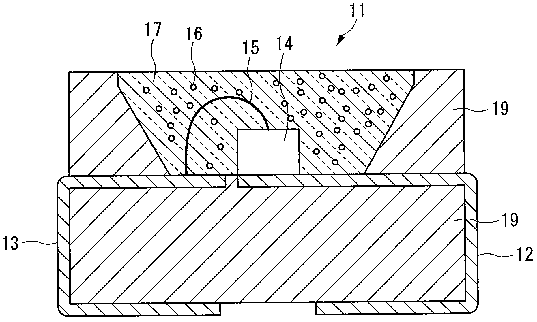
Image

Examples
example 1
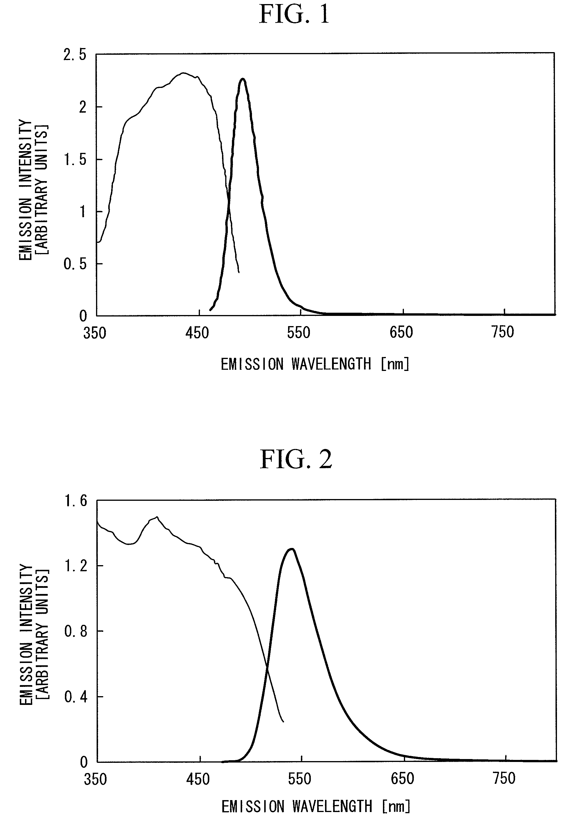
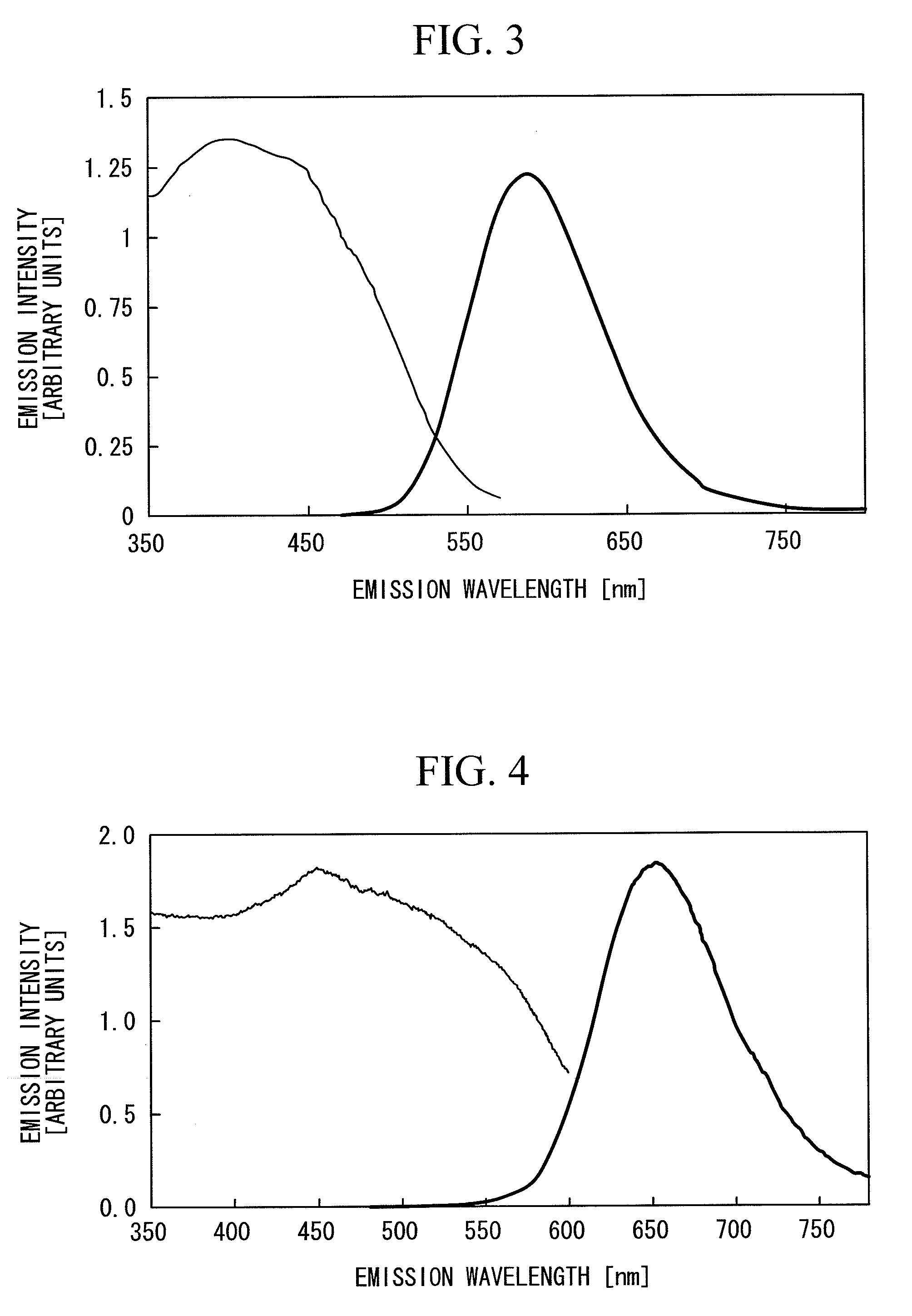
[0056]First is a description of the first fluorescent material. The first fluorescent material is a europium-activated oxynitride crystal fluorescent material represented by a formula Bax(1−r)SiyOzN(2x+4y−2z) / 3:Euxr, which emits either a blue-green light or a green light upon blue light excitation. Synthesis of this oxynitride crystal fluorescent material represented by Bax(1−r)SiyOzN(2x+4y−2z) / 3:Euxr is conducted in the manner described below.
[0057]First a calcination was conducted using Si3N4 powder, SiO2 powder, BaCO3 powder and Eu2O3 powder as raw material powders. On the basis of the targeted composition, it may be thought that the use of barium nitride or barium oxide would be appropriate for the barium component, but barium nitride is extremely expensive, making it unsuitable for industrial application, whereas barium oxide tends to be partially converted to barium hydroxide and barium carbonate under the action of moisture or carbon dioxide in the air, meaning accurate weigh...
example 2
[0088]In this example, the same first fluorescent material that emits a blue-green light, second fluorescent material that emits a green light, third fluorescent material that emits a yellow-red light and fourth fluorescent material that emits a red light as those used in the above Example 1 were used, and the mixing ratio between these first to fourth fluorescent materials was set to a mass ratio of 9:12:8:3, thereby yielding an emission chromaticity with a warm white color.
[0089]The warm white color refers to a range, within a CIE 1931 XYZ color space chromaticity diagram, represented by the quadrilateral shape connecting the four points at coordinates (x, y) of (0.4341, 0.4233), (0.4171, 0.3846), (0.4021, 0.4076) and (0.3903, 0.3719).
[0090]With the exception of this change, a warm white LED lamp was prepared in the same manner as Example 1, and the emission spectrum of the lamp was measured.
[0091]The warm white LED lamp of this example had a warm white color with coordinates (x, ...
example 3
[0094]In this example, the same first fluorescent material that emits a blue-green light, second fluorescent material that emits a green light, third fluorescent material that emits a yellow-red light and fourth fluorescent material that emits a red light as those used in the above Example 1 were used, and the mixing ratio between these first to fourth fluorescent materials was set to a mass ratio of 4.5:5:3:1, thereby yielding an emission chromaticity with a white color.
[0095]The white color refers to a range, within a CIE 1931 XYZ color space chromaticity diagram, represented by the quadrilateral shape connecting the four points at coordinates (x, y) of (0.3938, 0.4097), (0.3805, 0.3642), (0.3656, 0.3905) and (0.3584, 0.3499).
[0096]With the exception of this change, a white LED lamp was prepared in the same manner as Example 1, and the emission spectrum of the lamp was measured.
[0097]The white LED lamp of this example had a white color with coordinates (x, y) of (0.376, 0.378) in ...
PUM
 Abstract
Description
Claims
Application Information