Transcutaneous prosthesis

a prosthesis and transcutaneous technology, applied in the field of transcutaneous prosthesis, can solve the problems of difficult healing, pressure sores, and use of endo-prosthetic devices, and achieve the effects of facilitating the integration of components, increasing external surface area, and increasing the torqu

Inactive Publication Date: 2009-06-11
UNIV COLLEGE OF LONDON
View PDF14 Cites 15 Cited by
  • Summary
  • Abstract
  • Description
  • Claims
  • Application Information

AI Technical Summary

Benefits of technology

[0011]The prosthesis provided by the present invention is thus an intra-osseous transcutaneous prosthesis (ITAP) and has a number of advantages. For example, the first component is attached directly to load-bearing parts of the bony skeleton such that load is transmitted through bone. This means that the patient is able to apply much more power to the prosthesis. Also, motion and perception of movement is more natural because of the bone attachment. Moreover, because the skin takes no part in transmitting the load from the bone to the external part of the prosthesis, there is no pressure on the skin surface which would cause inflammation or discomfort.
[0013]The second component extends between the bone and the epithelial surface. This component is provided with a surface treatment for stimulating fibrous tissue ingrowth. Again, this component may be treated with an hydroxyapatite or aluminium oxide coating and the coating treated with materials which encourage the adhesion of epithelial cells to the second component. This component may also have a coating which is porous to encourage soft tissue ingrowth materials which encourage such growth include adhesion promoting proteins such as fibronectin or laminin. In order to aid adhesion of the fibrous tissue to the second component, the hypodermis is preferably surgically removed during the procedure of installing the prosthesis. The goal is to attach the skin to the implant to prevent movement of the skin and shear forces separating epithelial cells at the interface and underlying dermis and thereby permitting infection to enter between the skin and the prosthesis.
[0016]The external component will preferably include a safety device comprising a linkage which breaks under an unusual load such as, for example, one caused by the patient falling. This will allow the external component to detach from the skeletal and transcutaneous component without causing damage to the bone or to the skin. An additional feature which will protect the fixation of an intramedullary post is an external device which limits torque transmitted to the adjustable fixation. The torque transmitted may be adjustable so that with time, the transmitted torque can be increased, as the internal component integrates with the bone.
[0017]In a further preferred embodiment of the present invention the second component may be provided so as to extend outwardly from the first and third components in a manner that increases the external surface area of the second component. The second component may also be provided with through holes which further increase the external surface area and allow growth of tissue through the second component. This has been found to advantageously facilitate the integration of the component with fibrous tissue growth.

Problems solved by technology

A number of disadvantages arise from the use of such endo-prosthetic devices.
(1) Skin is not a satisfactory high load bearing structure and often breaks down under load, becoming inflamed and uncomfortable and, in severe cases, pressure sores are formed which are difficult to heal.
(3) The use of sockets for receiving the stump are commonly sweaty and uncomfortable.
(4) Where a joint is involved, the external prosthesis is usually moved by muscle groups situated at a distance from the attached prosthesis and therefore motion is inefficient and unnatural.

Method used


Image

  • Transcutaneous prosthesis
  • Transcutaneous prosthesis
  • Transcutaneous prosthesis

Examples


Embodiment Construction

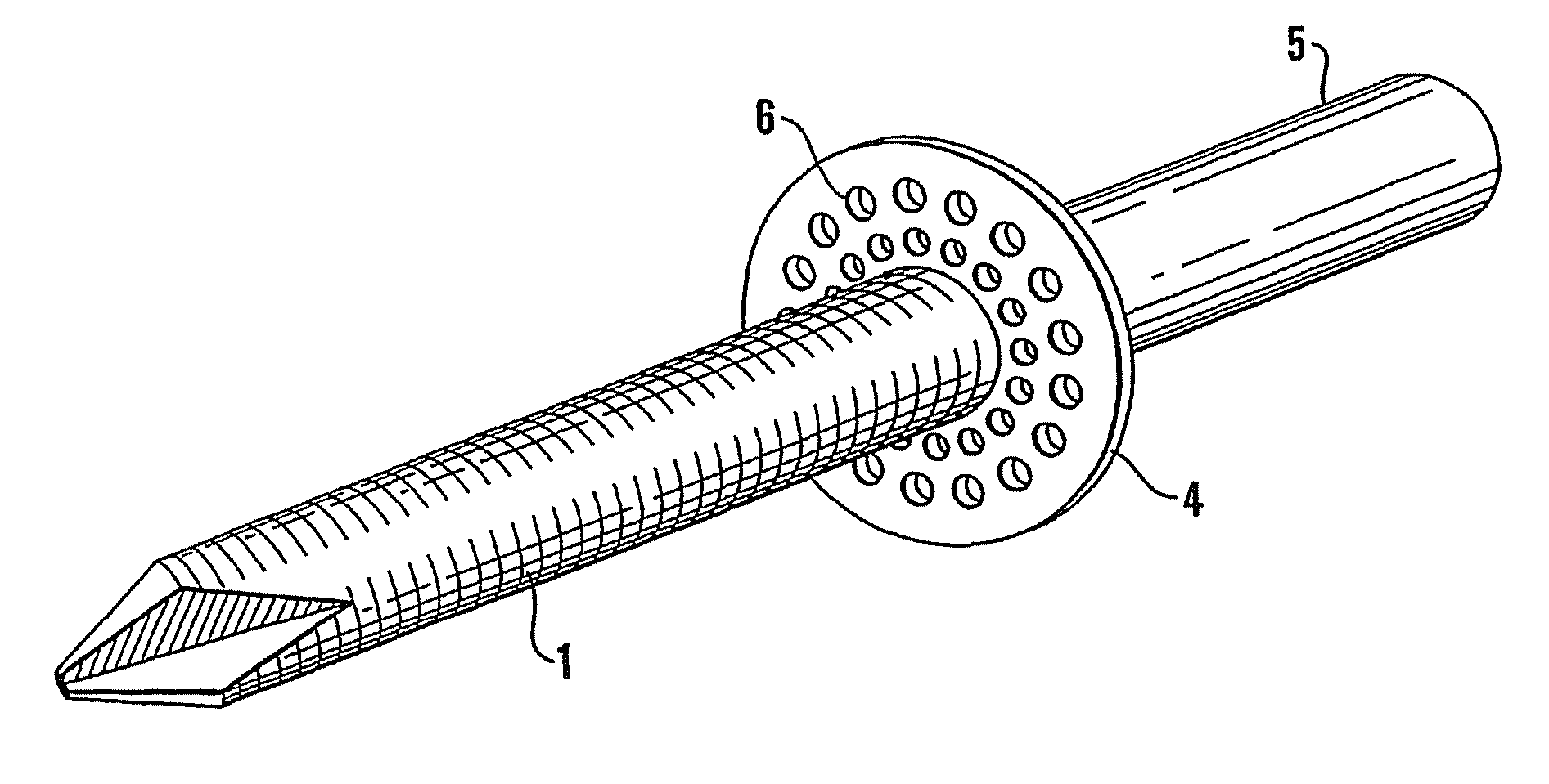
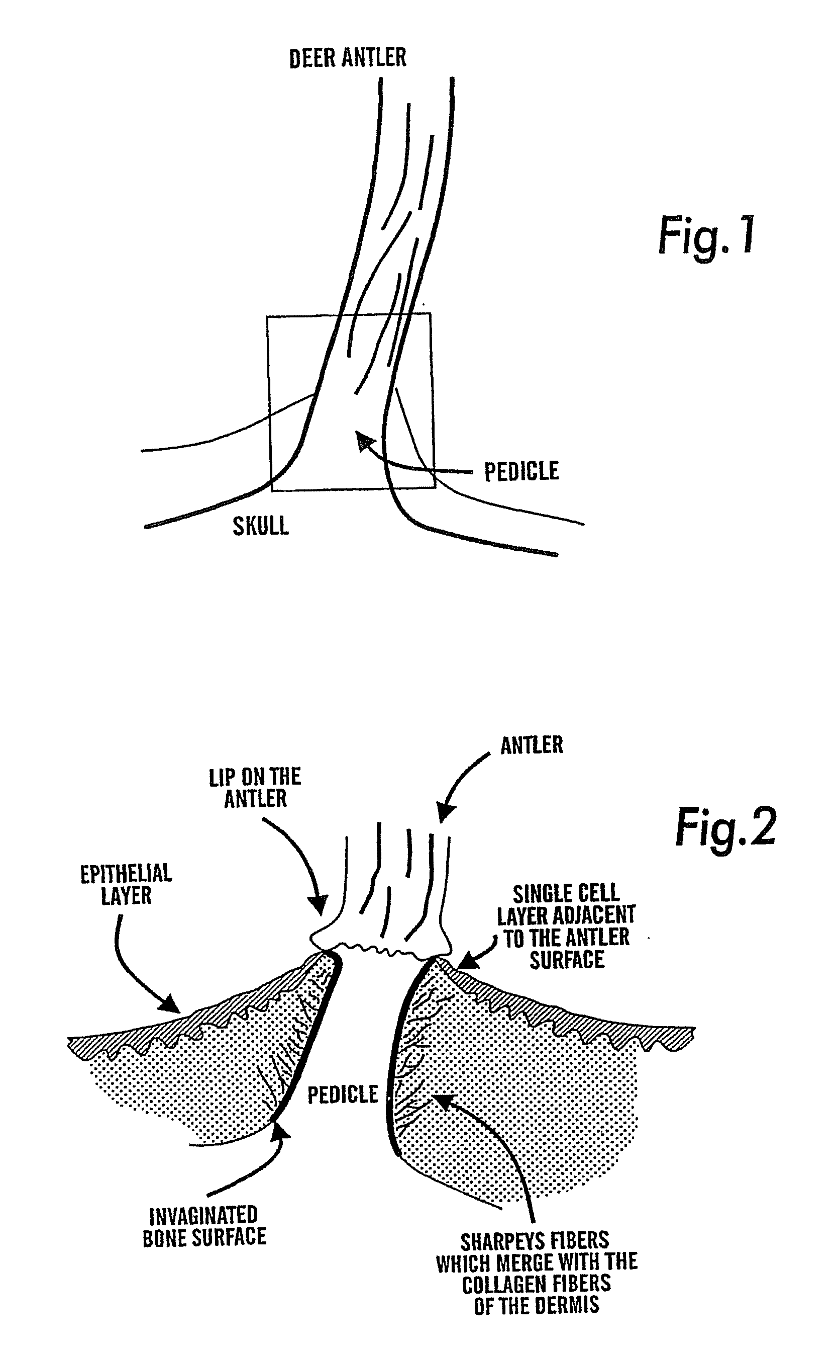
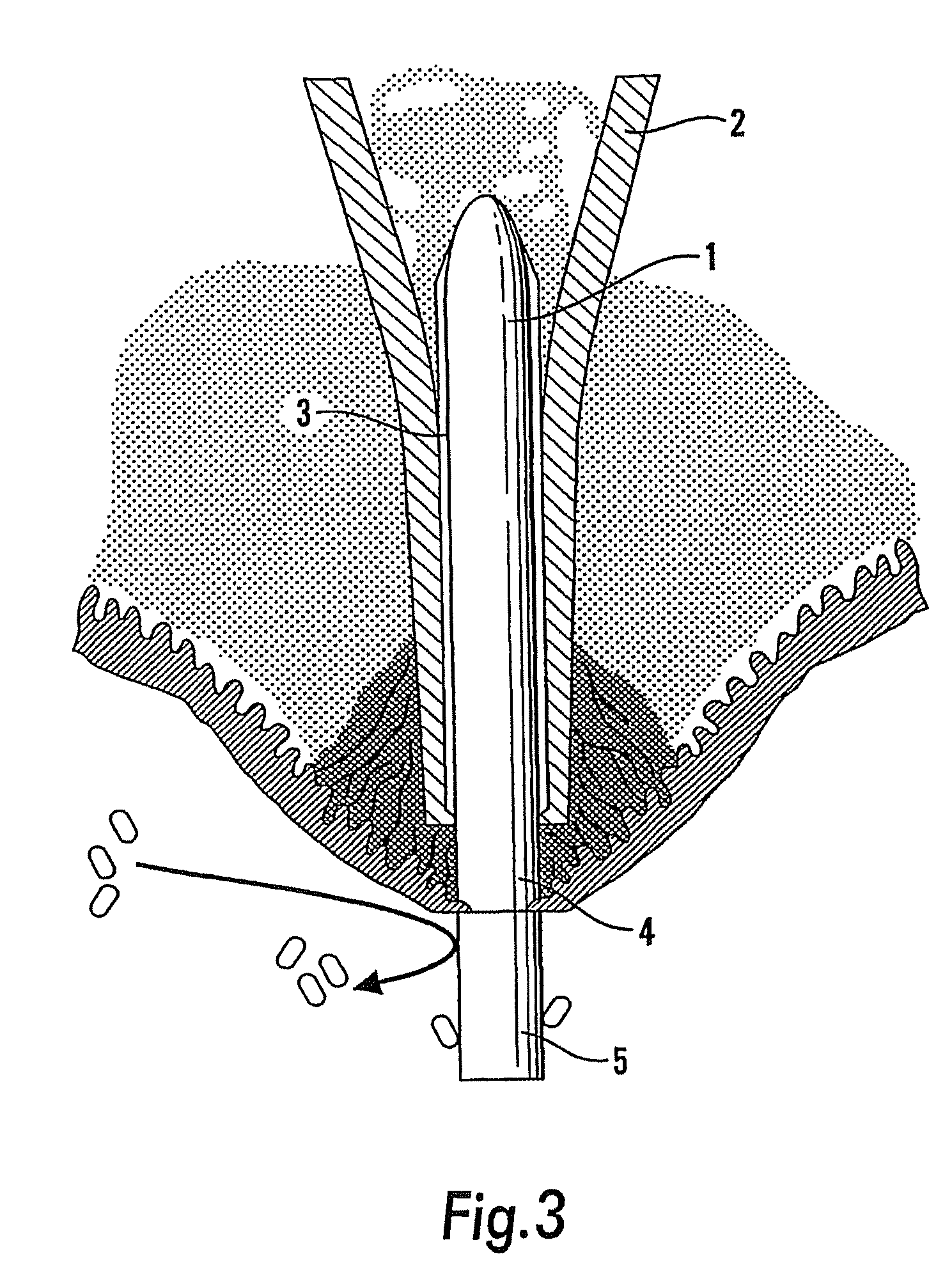
[0022]Referring to the drawings, the present invention was in part stimulated by study of the skin-bone interface around red deer antlers. This is a unique structure and may be thought of as a biological model for a transcutaneous implant. The deer antler at periods of the year is very heavily loaded during the rut. Histological examination indicates that the layer of skin epithelial cells become thinner as the epithelial layer approaches the antler, such that at the antler-skin interface an epithelial skin layer is only about one cell thick. The dermis is intimately attached to the bone (pedicle) interface. The attachment is achieved through a series of “Sharpeys fibres” which attach to the dermis and to the bone and prevent differential skin movement. Antlers do not normally become infected and the bone structure is invaginated with small pores measuring 18 to 40 microns in diameter. This helps the interface between the dermis and the bone to resist shear stresses. These features ...


PUM

PropertyMeasurementUnit
sizeaaaaaaaaaa
sizeaaaaaaaaaa
diameteraaaaaaaaaa

Abstract

A transcutaneous prosthesis includes a first component configured for attachment to a bone, the first component including flutes or grooves on a surface thereof for deterring rotation of the prosthesis within a bone; a second component adapted for location between the bone and the skin, the second component having a surface treatment for stimulation of fibroblastic cell proliferation and attachment of epithelial cells; and a third component adapted for location to extend from the skin surface and is adapted to extend directly from the skin surface in use, the third component having a coating of a non-stick material on an outer surface thereof, the coating having a surface energy that is lower than a surface energy of the first and second components and which is low enough to deter bacterial adhesion.

Description

CROSS REFERENCE TO RELATED APPLICATIONS[0001]The present application is a continuation of U.S. application Ser. No. 11 / 306,584, filed Jan. 3, 2006, which is a continuation of U.S. application Ser. No. 10 / 311,589, filed on Apr. 28, 2003, which is now U.S. Pat. No. 7,014,661, which is a national stage filing of PCT / GB01 / 02771, filed on Jun. 22, 2001, which claims the priority of GB 0015479.9, which was filed on Jun. 23, 2000.FIELD OF THE INVENTION[0002]This invention relates to transcutaneous prosthesis and includes a method of fitting a prosthesis having a transcutaneous component to a patient.BACKGROUND OF THE INVENTION[0003]Amputation of limbs or digits can occur due to trauma or because of surgical removal. Examples of trauma include loss of fingers in machinery accidents, loss of limbs in car accidents or as a result of land mine explosions. Surgical removal can also be indicated as a result of cardiovascular disease, diabetes and cancerous tumours to the bone or soft tissues.[00...

Claims


Application Information

Patent Timeline
Patent Type & Authority Applications(United States)
IPC IPC(8): A61F2/28A61B17/86A61F2/78A61L27/00A61C8/00A61F2/00A61F2/30A61F2/54A61F2/58A61F2/60A61F2/66A61L27/28A61L27/30A61L27/34
CPCA61C8/0006A61F2/60A61C8/0018A61F2/2814A61F2/30749A61F2/30767A61F2/78A61F2002/0086A61F2002/30224A61F2002/30225A61F2002/30322A61F2002/30558A61F2002/3056A61F2002/30561A61F2002/30574A61F2002/30604A61F2002/30785A61F2002/30838A61F2002/30848A61F2002/30878A61F2002/30879A61F2002/30929A61F2002/3093A61F2002/30981A61F2002/7887A61F2230/0069A61F2250/0026A61F2250/0073A61F2250/0074A61F2310/0058A61F2310/00604A61F2310/00796A61F2310/00976A61L27/28A61L27/303A61L27/34A61C8/0012A61F2/54C08L89/00A61L2430/02A61F2/3094A61F2002/30845A61F2/28A61F2/0077A61F2002/0081A61F2002/009
Inventor BLUNN, GORDONCOBB, JUSTINGOODSHIP, ALLENUNWIN, PAUL
Owner UNIV COLLEGE OF LONDON
Why Eureka
Try Eureka