

Failure detection device for power circuit including switching element
a technology of failure detection and power circuit, which is applied in emergency protective arrangements for limiting excess voltage/current, power supply testing, instruments, etc., can solve the problems of power module overload, high possibility of short-circuiting between the main electrodes of the switching element, and obviation of damage at the switching elemen
- Summary
- Abstract
- Description
- Claims
- Application Information
AI Technical Summary
Benefits of technology
Problems solved by technology
Method used
Image

Examples
first embodiment
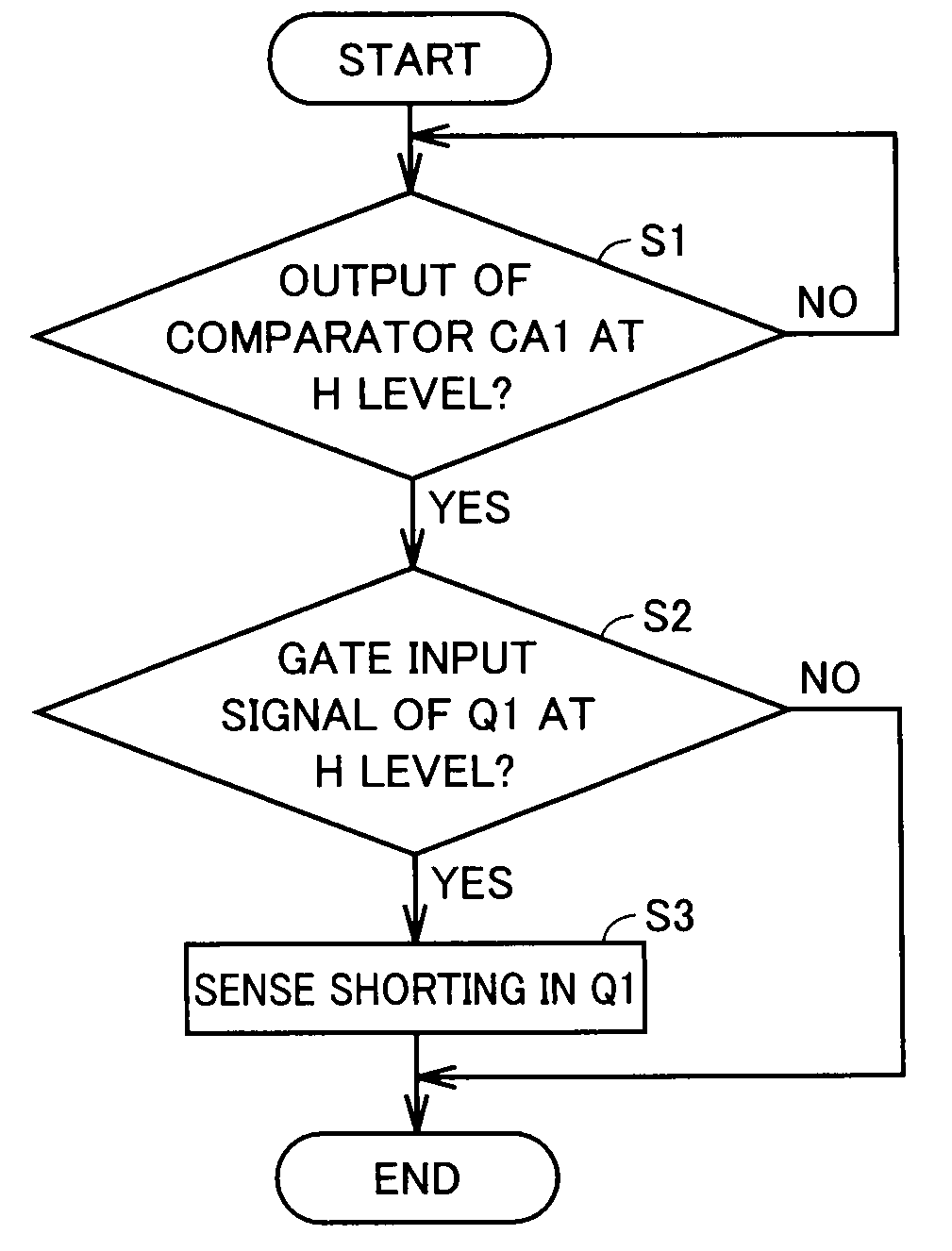
[0027]The first embodiment is directed to a failure detection device 1A detecting short-circuit failure in an IGBT.
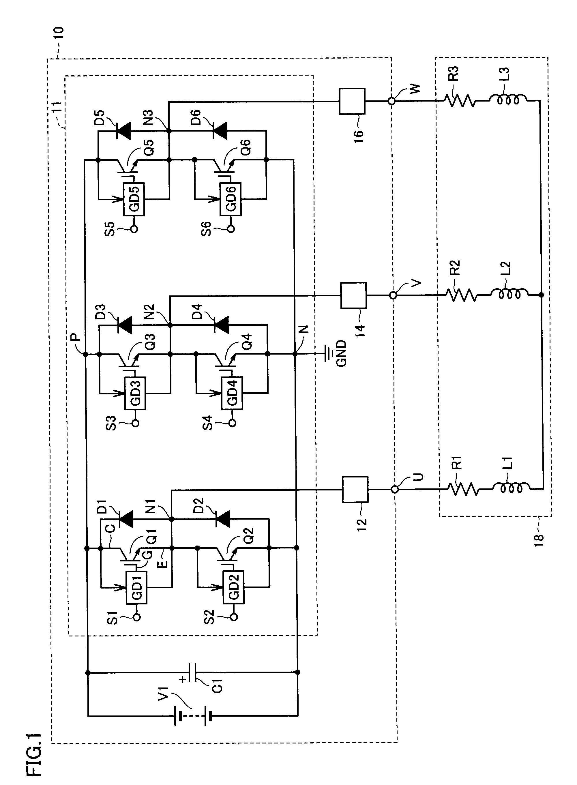
[0028]FIG. 1 is a diagram to describe a configuration of a motor drive device 10 to which the failure detection device of the first embodiment is applied.
[0029]Referring to FIG. 1, motor drive device 10 supplies three-phase AC (alternating current) power to a motor 18 from output nodes U, V, and W. Motor 18 is a three-phase AC motor, equivalently represented by resistances R1, R2, and R3 of the winding and inductors L1, L2 and L3 of the winding for each phase.
[0030]Motor drive device 10 includes a DC (direct current) power supply V1, a capacitor C1 connected parallel to DC power supply V1 for smoothing, an inverter circuit 11, and breakers 12, 14 and 16. An AC power supply and rectifying circuit can be employed instead of DC power supply V1.
[0031]Inverter circuit 111 is a three-phase bridge circuit, including two N channel IGBTs (IGBT Q1 and IGBT Q2 for the U phase, IGB...
second embodiment
[0070]FIG. 5 is a circuit diagram of a configuration of a failure detection device 1B according to a second embodiment of the present invention. Failure detection device 1B of FIG. 5 is a modification of failure detection device 1A of the first embodiment, and detects short-circuit failure in IGBT Q1. In the circuit diagram of FIG. 5, common potential VN1 qualified as the reference potential corresponds to the potential of emitter E (node N1) of IGBT Q1. A gate drive circuit and a failure detection device of the same configuration are provided for each of IGBT Q1-IGBT Q6. Therefore, a gate drive circuit GD1B and a failure detection device 1B provided for IGBT Q1 will be described representative thereof.
[0071]Referring to FIG. 5, gate drive circuit GDB1 includes a failure detection device 1B and a drive circuit UA. Failure detection device 1B includes a diode D7 with high breakdown voltage, a resistance element R4, a DC power supply V2, and a failure determination unit 2B. Failure de...
third embodiment
[0098]FIG. 7 is a circuit diagram of a configuration of a failure detection device 1C according to a third embodiment of the present invention. Failure detection device 1C of FIG. 7 is a modification of failure detection device 1B of the second embodiment, and detects the occurrence of short-circuit failure in IGBT Q1. A gate drive circuit and a failure detection device of the same configuration are provided for each of IGBT Q1-IGBT Q6. Therefore, a gate drive circuit GD1C and a failure detection device 1C provided for IGBT Q I will be described representative thereof.
[0099]Referring to FIG. 7, gate drive circuit GD1C includes a failure detection device 1C and a drive circuit UA. Failure detection device 1C of FIG. 7 differs from failure detection device 1B of FIG. 5 in the further inclusion of a logic circuit LA1. The remaining elements of failure detection device 1C of FIG. 7 are common to those of failure detection device 1B of FIG. 5. Therefore, description of common elements wi...
PUM
 Abstract
Description
Claims
Application Information