
Passivation layer structure of solar cell and fabricating method thereof

a solar cell and passivation layer technology, applied in the field of photoelectric devices, can solve the problems of inexhaustible solar energy without pollution, energy attracts most attention, etc., and achieve the effect of increasing the photoelectric conversion efficiency of the solar cell and enhancing the passivation effect of the passivation layer

Inactive Publication Date: 2009-07-02
IND TECH RES INST
View PDF1 Cites 84 Cited by
  • Summary
  • Abstract
  • Description
  • Claims
  • Application Information

AI Technical Summary

Benefits of technology

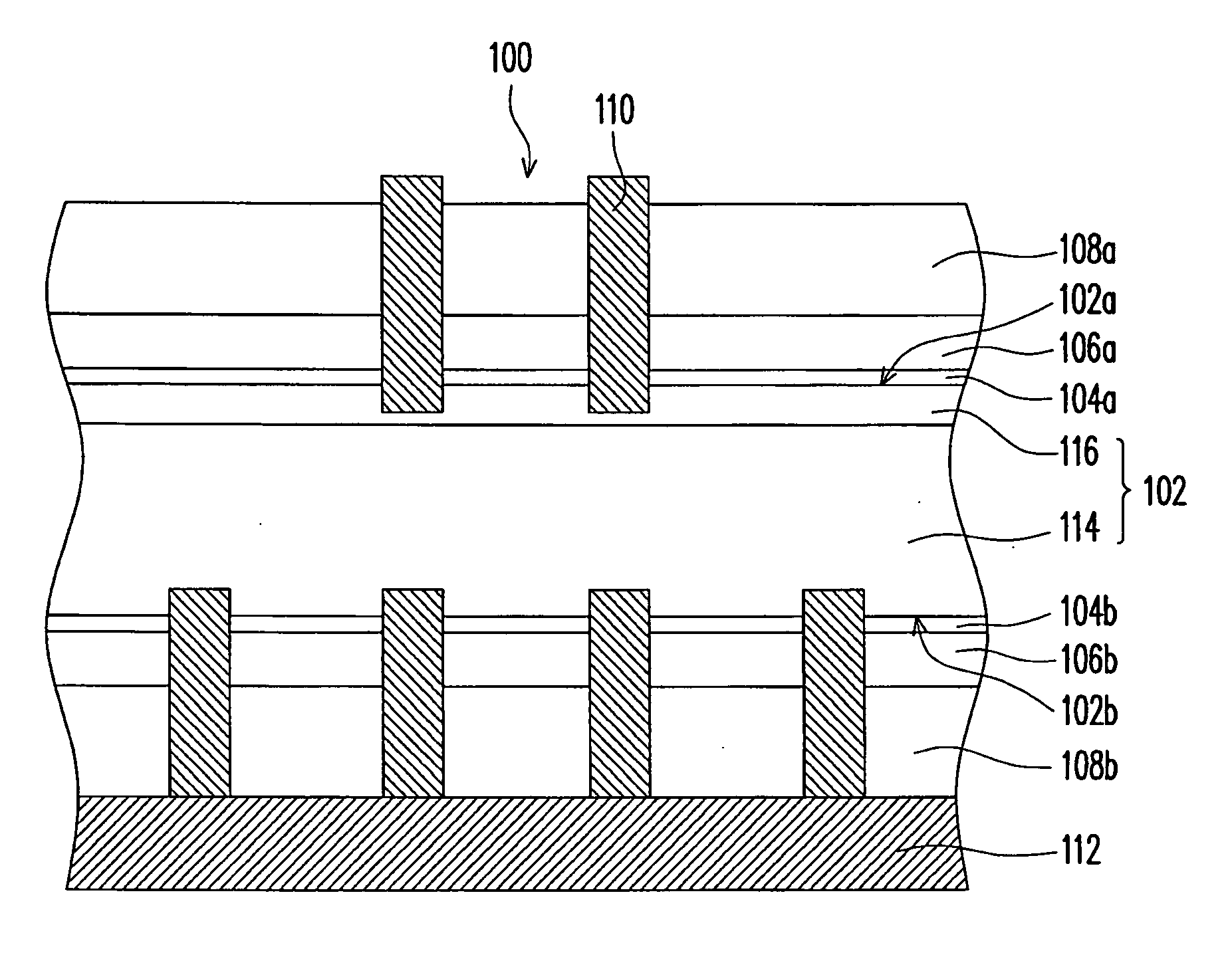
[0008]Accordingly, the present invention is directed to a passivation layer structure of a solar cell, which is capable of improving the surface passivation effect and directly improving the photoelectric conversion efficiency of the solar cell.
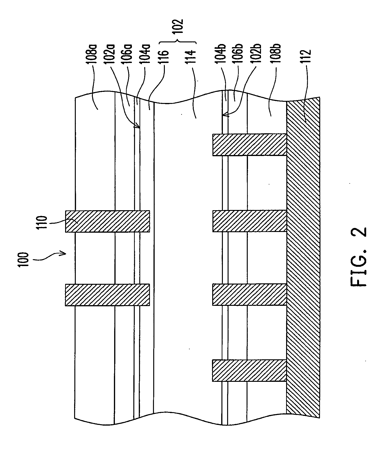
[0011]In the structure of the present invention, the second passivation layer is disposed between the substrate and the first passivation layer, so as to enhance the passivation effect of the passivation layer, thereby greatly increasing the photoelectric conversion efficiency of the solar cell.

Problems solved by technology

Solar energy is an inexhaustible energy having no pollution.
As the petrochemical energy source encounters the pollution and energy shortage problems, the solar energy attracts most of the attentions.
Recently, it becomes a quite important research issue to directly convert a solar cell into electric energy.

Method used


Image

  • Passivation layer structure of solar cell and fabricating method thereof
  • Passivation layer structure of solar cell and fabricating method thereof
  • Passivation layer structure of solar cell and fabricating method thereof

Examples


experimental example 1

[0034]A layer of silicon oxide with a thickness of 2 nm is grown on a silicon wafer to serve as a second passivation layer, and then a layer of aluminium oxide with a thickness of 15 mn is coated by an ALD process to serve as a first passivation layer.

experimental example 2

[0039]The photoelectric conversion layer of the solar cell is formed by p-type poly-silicon wafer (mc-Si wafer) of 1*1020 cm−3 doped with B. The mean grain size of the poly-silicon wafer is approximately 5 mm. A pyramid structure is pre-fabricated on a surface of the wafer. The NP junction is finished by performing diffusion for 20 minutes at 850° C. by using phosphorus oxychloride (POCl3). Then, the passivation layer is respectively formed on the front and back surfaces of the wafer. The passivation layer is formed by a second passivation layer and a first passivation layer, and the forming process thereof includes: firstly, a layer of silicon oxide with a thickness of 2 nm is grown on the front and back surfaces of the poly-silicon wafer to serve as the second passivation layer, and then a layer of aluminium oxide with a thickness of 15 nm is coated by the ALD process to serve as the first passivation layer. An anti-reflection layer is respectively formed on the front and back sur...


PUM


Abstract

A passivation layer structure of a solar cell, disposed on a substrate, is provided. The passivation layer structure has a first passivation layer and a second passivation layer. The first passivation layer is disposed on the substrate. The second passivation layer is disposed between the substrate and the first passivation layer, and the material of the second passivation layer is an oxide of the material of the substrate. Since the second passivation layer is disposed between the substrate and the first passivation layer, the surface passivation effect and carrier lifetime of a photoelectric device are enhanced, and a photoelectric conversion efficiency of the solar cell is increased as well.

Description

CROSS-REFERENCE TO RELATED APPLICATION[0001]This application claims the priority benefit of Taiwan application serial no. 96151035, filed on Dec. 28, 2007. The entirety of the above-mentioned patent application is hereby incorporated by reference herein and made a part of this specification.BACKGROUND OF THE INVENTION[0002]1. Field of the Invention[0003]The present invention generally relates to a photoelectric device, in particular, to a passivation layer structure of a solar cell, which is capable of improving a photoelectric conversion efficiency, and a fabricating method thereof.[0004]2. Description of Related Art[0005]Solar energy is an inexhaustible energy having no pollution. As the petrochemical energy source encounters the pollution and energy shortage problems, the solar energy attracts most of the attentions. Recently, it becomes a quite important research issue to directly convert a solar cell into electric energy.[0006]Silicon-based solar cell is a common solar cell in ...

Claims


Application Information

Patent Timeline
Patent Type & Authority Applications(United States)
IPC IPC(8): H01L31/0264H01L31/04H01L31/18
CPCH01L31/02167Y02E10/50H01L31/1868Y02P70/50
Inventor SUN, WEN-CHINGCHEN, CHIEN-HSUNLAN, CHUNG-WENHUANG, CHIEN-RONG
Owner IND TECH RES INST
Learn More