Apparatus and Method for Deep Ultraviolet Optical Microscopy

Active Publication Date: 2009-07-02
THE ARIZONA BOARD OF REGENTS ON BEHALF OF THE UNIV OF ARIZONA +1
View PDF25 Cites 50 Cited by
  • Summary
  • Abstract
  • Description
  • Claims
  • Application Information

AI Technical Summary

Benefits of technology

[0010]The present inventors have recognized that an improved optical microscope (and / or related imaging system and / or method of performing optical microscopy) suitable for viewing many small features can be achieved in at least some embodiments by utilizing the intense, substantially monochromatic and isolated radiation of the atomic Hydrogen resonance line at 121.6 nm (the Hydrogen Lyman-α line) in the deep or vacuum ultraviolet region of the electromagnetic spectrum (e.g., λ<190 nm).The present inventors have further recognized that the use of light at this wavelength is advantageous in several regards. More particularly, the present inventors have recognized that there is a narrow, highly transparent “window” in the air absorption spectrum, also precisely at 121.6 nm, such that light emitted at the Hydrogen Lyman-α line from a light source can be effectively transmitted within the optical microscope without the need to work in high vacuum. Additionally, the present inventors have recognized that effective light sources and optical components can be developed for giving off and transmitting strong, relatively-monochromatic light at the Hydrogen Lyman-α line.

Problems solved by technology

Also, optical microscopy does not involve evaporating coating onto the samples, or evacuating the sample chamber, both of which can be time consuming.
Notwithstanding the advantages of optical microscopes relative to electron microscopes such as those described above, in recent years there has been a significant decline in the sale of optical microscopes.
A number of techniques involving shorter-wavelength light have been considered, yet these techniques suffer from various disadvantages.
For example, while an optical microscope employing light within the near ultraviolet range (approximately 200 nm<λ<400 nm) may provide some wavelength advantage over a visible light optical microscope, the difficulties of image display and aberrations in optical components may not justify that advantage.
However, it is difficult energetically to dissociate Nitrogen and then form the N+6 ion in an electronically excited state.
Indeed, to perform such a process and thereby generate light at the desired wavelength, complicated methods and equipment such as pinched plasma sources and high-powered pulsed lasers are necessary.
Implementation of a microscope in a manner such that light is transmitted within a high vacuum, however, can be challenging and costly.

Method used


Image

  • Apparatus and Method for Deep Ultraviolet Optical Microscopy
  • Apparatus and Method for Deep Ultraviolet Optical Microscopy
  • Apparatus and Method for Deep Ultraviolet Optical Microscopy

Examples


Embodiment Construction

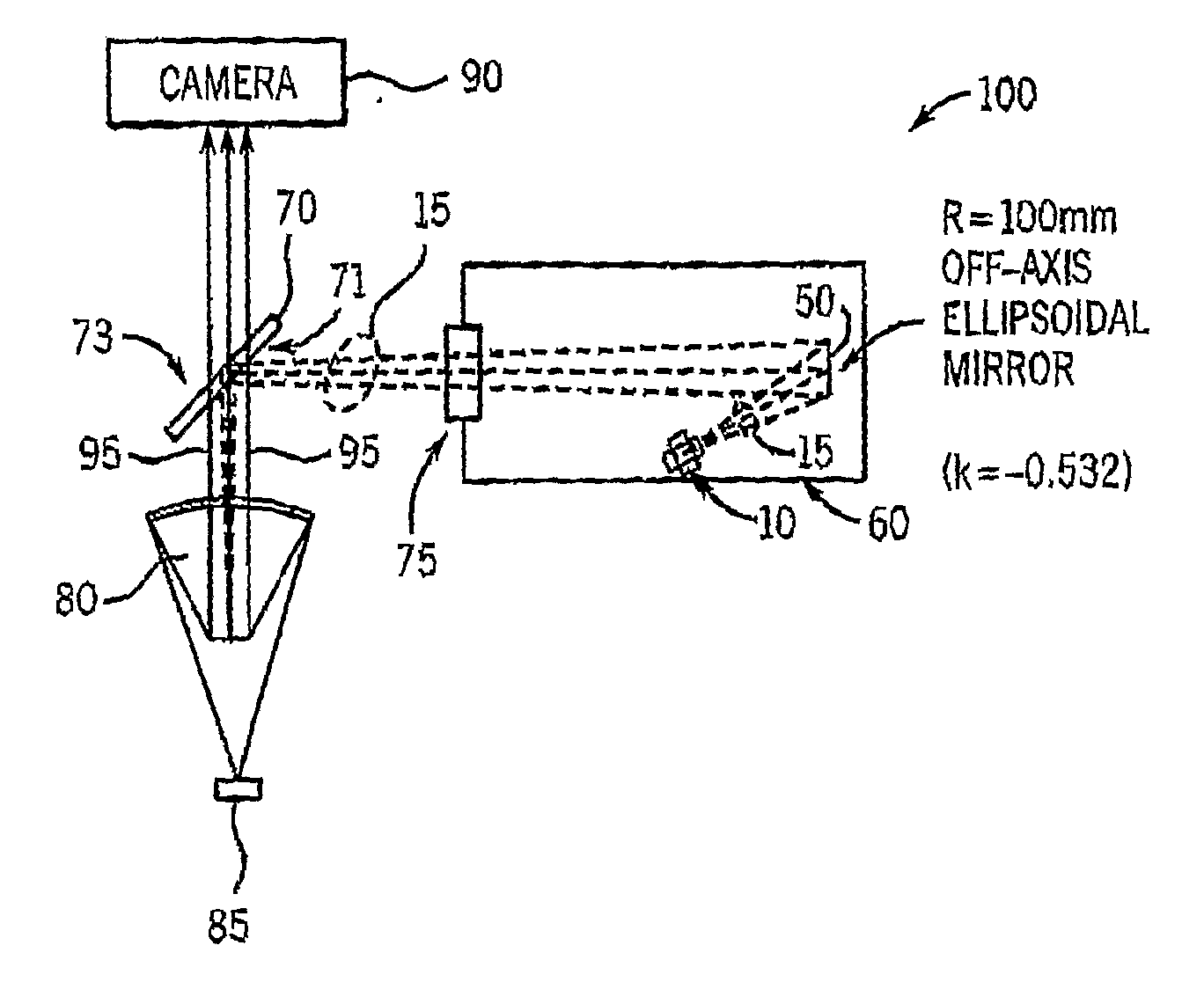
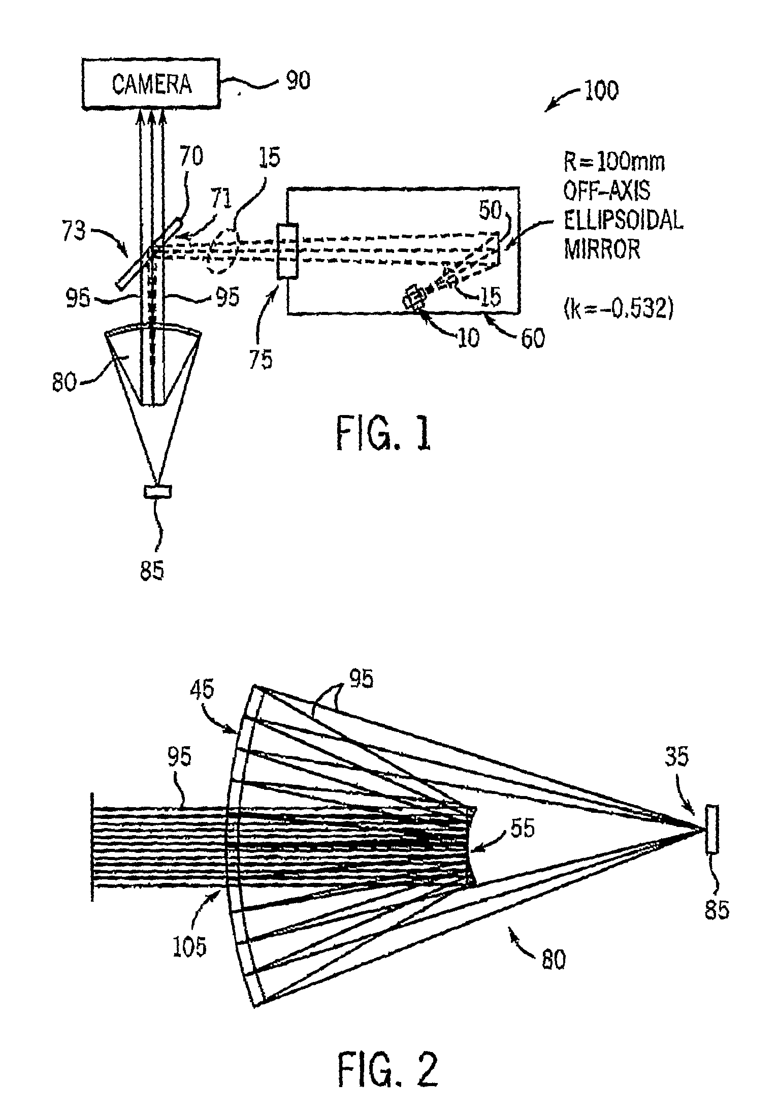
[0025]FIG. 1 illustrates, in simplified schematic form, exemplary components of an optical microscope 100, in accordance with at least one embodiment of the present invention. As will be described in further detail below, the optical microscope 100 operates through the use of light at the Hydrogen Lyman-α line, that is, light at (or approximately at) a wavelength of 121.6 nm. This wavelength is in the “vacuum ultraviolet” and “deep ultraviolet” regions of the electromagnetic spectrum, which generally overlap one another, albeit the vacuum ultraviolet region is generally understood to extend from the region of strong absorption by molecular Oxygen near about 190 nm to the “Soft” X-ray region near 20 nm while the deep ultraviolet region is generally understood to extend to wavelengths somewhat higher than 190 nm (e.g., up to nearly 200 (e.g., 193) or 250 (e.g., 248) nm. Further as will be described below, utilization of light at the Hydrogen Lyman-α line should provide about a five-fo...


PUM


Abstract

An apparatus and method for performing optical microscopy are disclosed. In at least one embodiment, the apparatus includes a deep ultraviolet light source configured to generate light having a wavelength within a window in the deep ultraviolet region of the electromagnetic spectrum within which a local minimum in the absorption coefficient of Oxygen occurs. Further, the apparatus includes a lens device that receives at least a first portion of the generated light, directs at least some of the first portion of the generated light toward a location, receives reflected light from the location, and directs at least some of the reflected light toward a further location. Additionally, the apparatus includes a camera device that is positioned at one of the further location and an additional location, where the camera device receives at least a second portion of the reflected light, whereby an image is generated by the camera device.

Description

CROSS-REFERENCE TO RELATED APPLICATIONS[0001]This application claims the benefit of U.S. provisional patent application No. 60 / 812,912 entitled “Method and Apparatus for Deep Ultraviolet Microscopy” filed on Jun. 13, 2006, which is hereby incorporated by reference herein.STATEMENT REGARDING FEDERALLY SPONSORED RESEARCH OR DEVELOPMENT[0002]1. Field of the Invention[0003]The present invention relates to optical microscopy and, more particularly, to methods and apparatuses for optical microscopy that employ light at wavelengths outside of the visible light spectrum.[0004]2. Background of the Invention[0005]Optical microscopes have numerous applications in both the physical sciences as well as in the life sciences. In semiconductor manufacturing for example, visible light microscopes are used for inspecting semiconductor wafers following many of the several hundred process steps employed to fabricate semiconductor devices. This optical wafer inspection technique has advantages over the ...

Claims


Application Information

Patent Timeline
IPC IPC(8): G02B21/06G02B13/14
CPCG02B21/16
Inventor GELERNT, BARRYMILSTER, THOMAS D.
Owner THE ARIZONA BOARD OF REGENTS ON BEHALF OF THE UNIV OF ARIZONA
Why Eureka
Try Eureka