Fuel cell system

a fuel cell and system technology, applied in the field of fuel cell systems, can solve the problems of relatively low thermal stress on the fuel cell(s), relative low heat generation at the fuel cell(s) of the fuel cell system, etc., and achieve the effects of improving system efficiency, high fuel concentration, and high fuel concentration

Inactive Publication Date: 2009-07-02
SAINT GOBAIN CERAMICS & PLASTICS INC
View PDF4 Cites 27 Cited by
  • Summary
  • Abstract
  • Description
  • Claims
  • Application Information

AI Technical Summary

Benefits of technology

[0007]With the present invention, near 100% fuel utilization can be achieved by recycling anode exhaust with carbon dioxide and water removal, significantly improving system efficiency. The relatively high fuel concentration due to recycling, with carbon dioxide removal and at least partial water removal, results in a relatively high fuel (e.g., H2, CO and CH4)-to-product (i.e., H2O and CO2) ratio, which can provide a relatively high open circuit voltage (OCV) and a relatively high cell voltage (high fuel cell efficiency). Generally, operating a fuel cell system at a relatively high cell voltage can provide relatively a long stack life. In addition, the operation of a fuel cell system at a relatively high cell voltage results in relatively low heat generation at the fuel cell(s) of the fuel cell system, and, in turn, relatively low thermal stress on the fuel cell(s).
[0008]The present invention can employ a water-gas-shift unit that converts carbon monoxide and water, from anode exhaust, into hydrogen gas and carbon dioxide (i.e., water splitting), wherein the generated carbon dioxide is removed at the carbon-dioxide-removal unit, together with the carbon dioxide from the fuel cell assembly. Water splitting increases the concentration of hydrogen gas, relative to the concentration of carbon-monoxide, of the recycle stream that is directed from the carbon-dioxide-removal unit to the fue

Problems solved by technology

In addition, the operation of a fuel cell system at a relatively high cell voltage results in relatively low heat gen

Method used


Image

  • Fuel cell system
  • Fuel cell system
  • Fuel cell system

Examples


Embodiment Construction

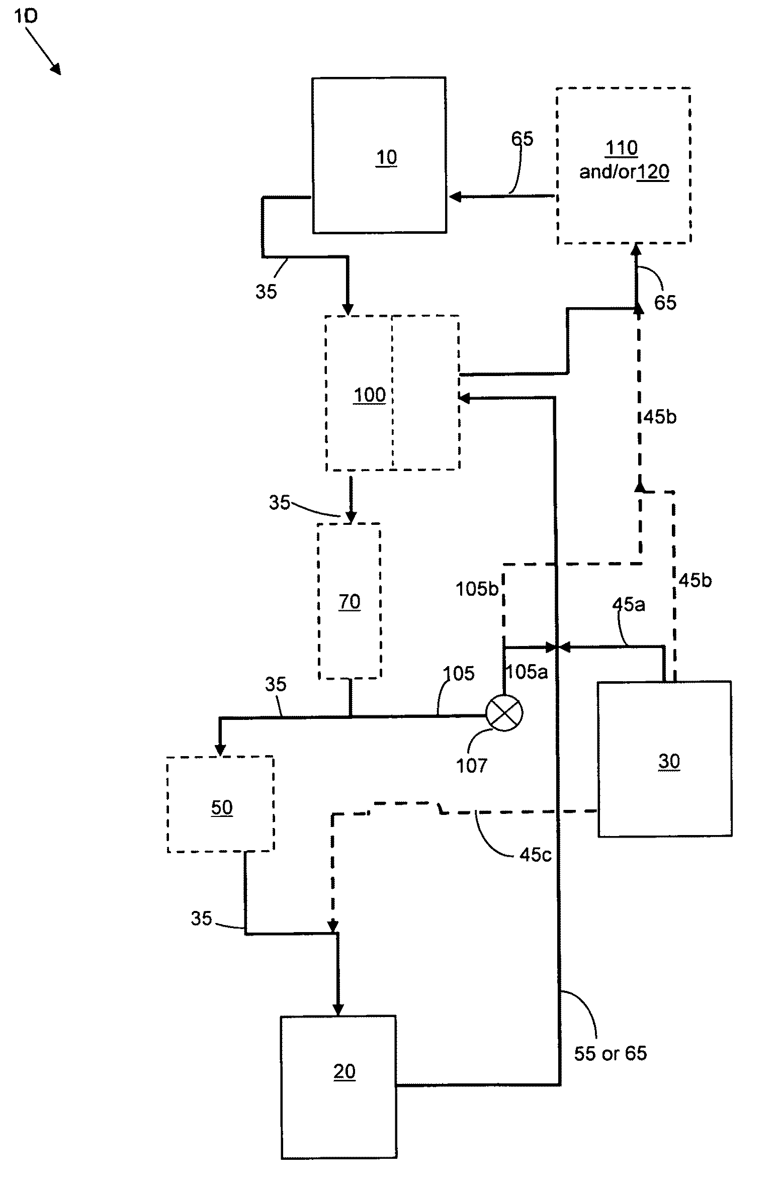
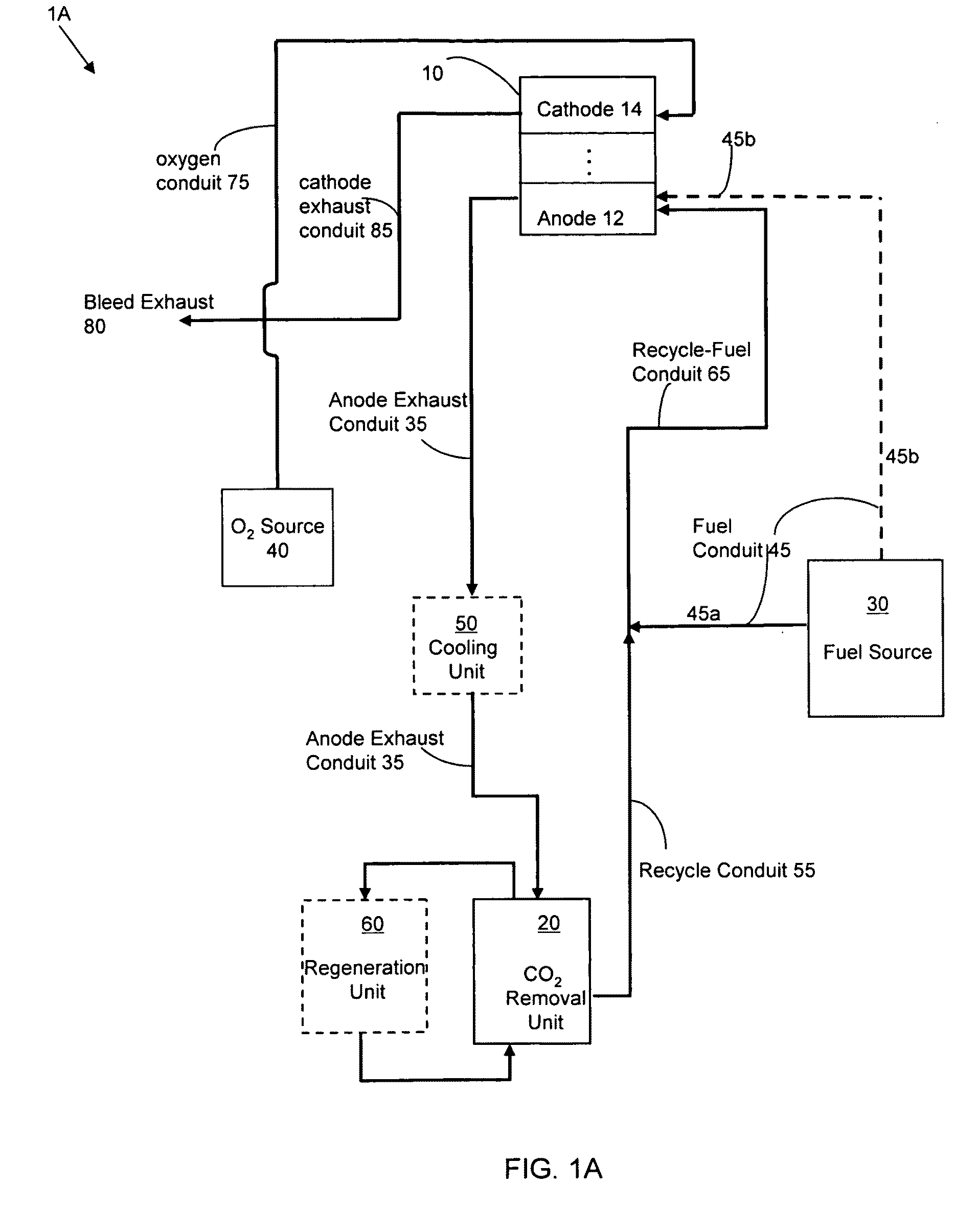
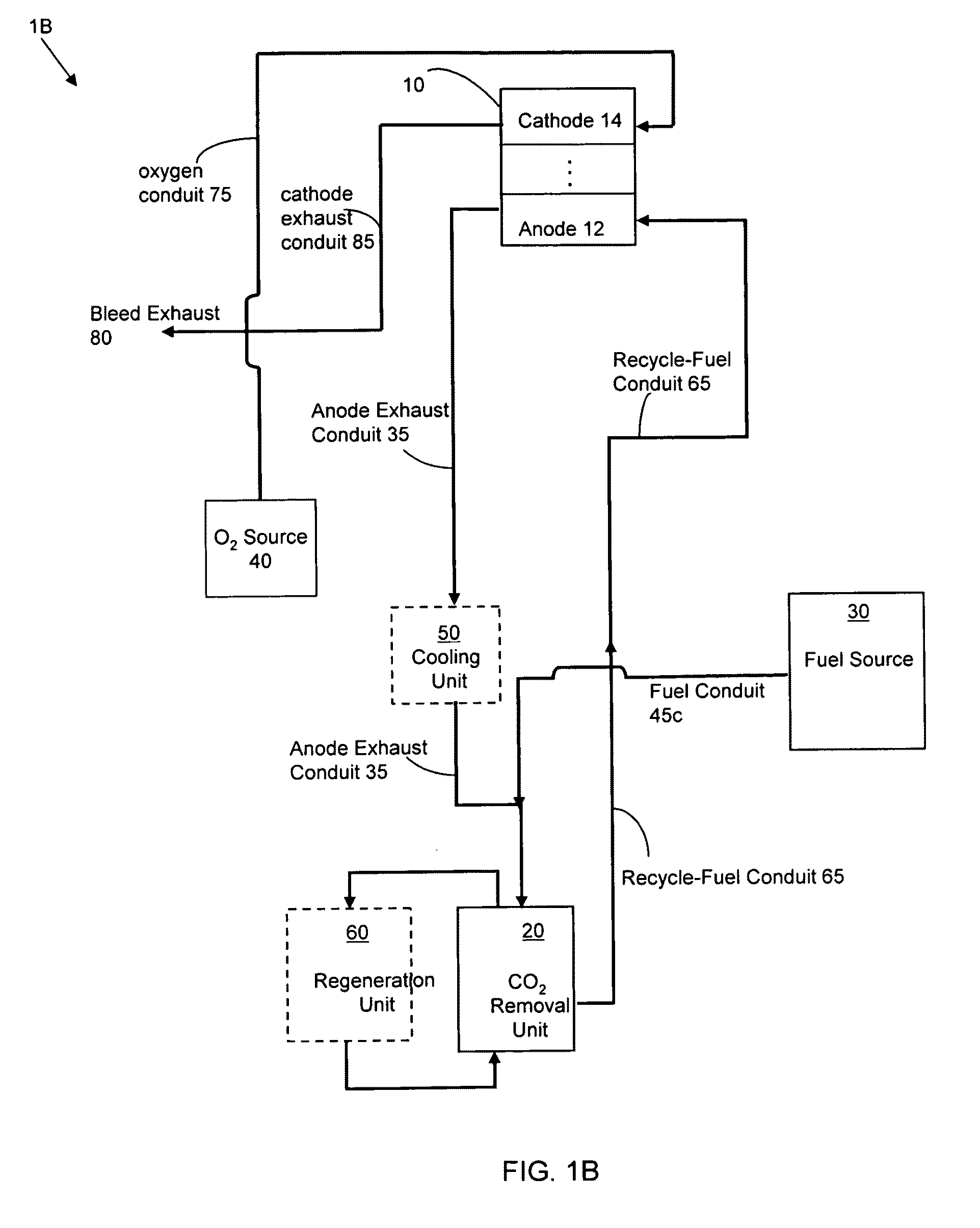
[0022]The foregoing will be apparent from the following more particular description of example embodiments of the invention, as illustrated in the accompanying drawings in which like reference characters refer to the same parts throughout the different views. The drawings are not necessarily to scale, emphasis instead being placed upon illustrating embodiments of the present invention. In the figures, an optional unit(s) or component(s), and an alternative conduit(s) are indicated with a dashed box and a dashed arrow, respectively.

[0023]FIGS. 1A and 1B show certain embodiments of the fuel cell systems of the invention, fuel cell system 1 (hereinafter, collectively referring to fuel cell system 1A-1B of FIGS. 1A-1B and fuel cell systems 1C-1F of FIGS. 2, 5 and 6 which are described below). Fuel cell system 1 includes fuel cell assembly 10; carbon-dioxide (CO2)-removal unit 20; anode exhaust conduit 35 connecting fuel cell assembly 10 and CO2-removal unit 20; fuel source 30 that is in...


PUM


Abstract

A fuel cell system comprises a fuel cell assembly, a carbon-dioxide-removal unit, an anode exhaust conduit connecting the fuel cell assembly and the carbon-dioxide-removal unit, a fuel source, an oxygen source, a fuel conduit connecting, at least in part, the fuel source with the fuel cell assembly, and a recycle conduit connecting the carbon-dioxide-removal unit with at least one of the fuel cell assembly, the fuel conduit and the fuel source. The fuel cell assembly includes at least one fuel cell, each fuel cell including an anode and a cathode. The carbon-dioxide-removal unit removes carbon dioxide that is in a gas phase. The carbon-dioxide-removal unit includes a carbon-dioxide-removing material. The fuel source and the oxygen source are each independently in fluid communication with the fuel cell assembly. The fuel conduit and the recycle conduit are optionally merged into a single recycle-fuel conduit that extends to the fuel cell assembly. The recycle conduit and/or the recycle-fuel conduit directs essentially all gaseous fluid from the carbon-dioxide-removal unit to the fuel cell assembly.

Description

RELATED APPLICATIONS[0001]This application claims the benefit of U.S. Provisional Application No. 61 / 009,418, filed on Dec. 28, 2007. The entire teachings of the above application is incorporated herein by reference.BACKGROUND OF THE INVENTION[0002]Fuel cells can offer potentially clean, quiet and efficient power generation. Unlike thermal energy based engines, fuel cells use an electrochemical or battery-like process to convert the chemical energy associated with the conversion of hydrogen gas (and carbon monoxide for high temperature fuel cells) into water (and carbon dioxide for high temperature fuel cells) into electricity. Among various types of fuel cells, solid oxide fuel cells (SOFC) use hard ceramic compounds of metal oxides (e.g., calcium or zirconium oxides) to form their components, for example, electrodes, electrolytes and interconnects. Typically, in solid oxide fuel cells, oxygen gas (O2) is reduced to oxygen ions (O2−) at the cathode, and a fuel gas, such as hydrogen...

Claims


Application Information

Patent Timeline
IPC IPC(8): H01M8/04H01M8/00
CPCB01D2257/504B01D2258/0208H01M8/04007H01M8/04097H01M8/04156Y02E60/525H01M8/0668H01M8/0675H01M2008/1293Y02C10/04Y02E60/50H01M8/0618Y02C20/40
Inventor QI, CHUNMING
Owner SAINT GOBAIN CERAMICS & PLASTICS INC
Why Eureka
Try Eureka