Grafts and stent grafts having a radiopaque beading

a radiopaque beading and graft technology, applied in the field of medical devices, can solve the problems of complicated delivery procedure, kinking of grafts, and the need for additional means for anchoring grafts, so as to facilitate the operation of operator's vision, reduce kinking of grafts, and provide structural rigidity to implant devices.

Inactive Publication Date: 2009-07-02
CR BARD INC
View PDF100 Cites 51 Cited by
  • Summary
  • Abstract
  • Description
  • Claims
  • Application Information

AI Technical Summary

Benefits of technology

[0017]Accordingly, a properly configured radiopaque beading can facilitate meeting the visual needs of an operator in addition to providing structural rigidity to an implant device. More specifically, a radiopaque beading coupled to a graft or stent graft device can provide the necessary visual cues to assist in the implantation, follow-up and treatment of the device. The radiopaque beading can also be configured to reduce kinking in a graft by providing sufficient structural support to the implant witho

Problems solved by technology

However, they may require additional means for anchoring the graft within the blood vessel, such as sutures, clamps, or similarly functioning elements to overcome retraction.
A problem can arise in delivering a graft via a sheath.
In particular, if there is any interference between the graft and the sheath, the delivery procedure is complicated by requiring additional manipulation of the graft to migrate through the sheath and to the site of the stenosis.
It is believed however that, that thes

Method used


Image

  • Grafts and stent grafts having a radiopaque beading
  • Grafts and stent grafts having a radiopaque beading
  • Grafts and stent grafts having a radiopaque beading

Examples


Embodiment Construction

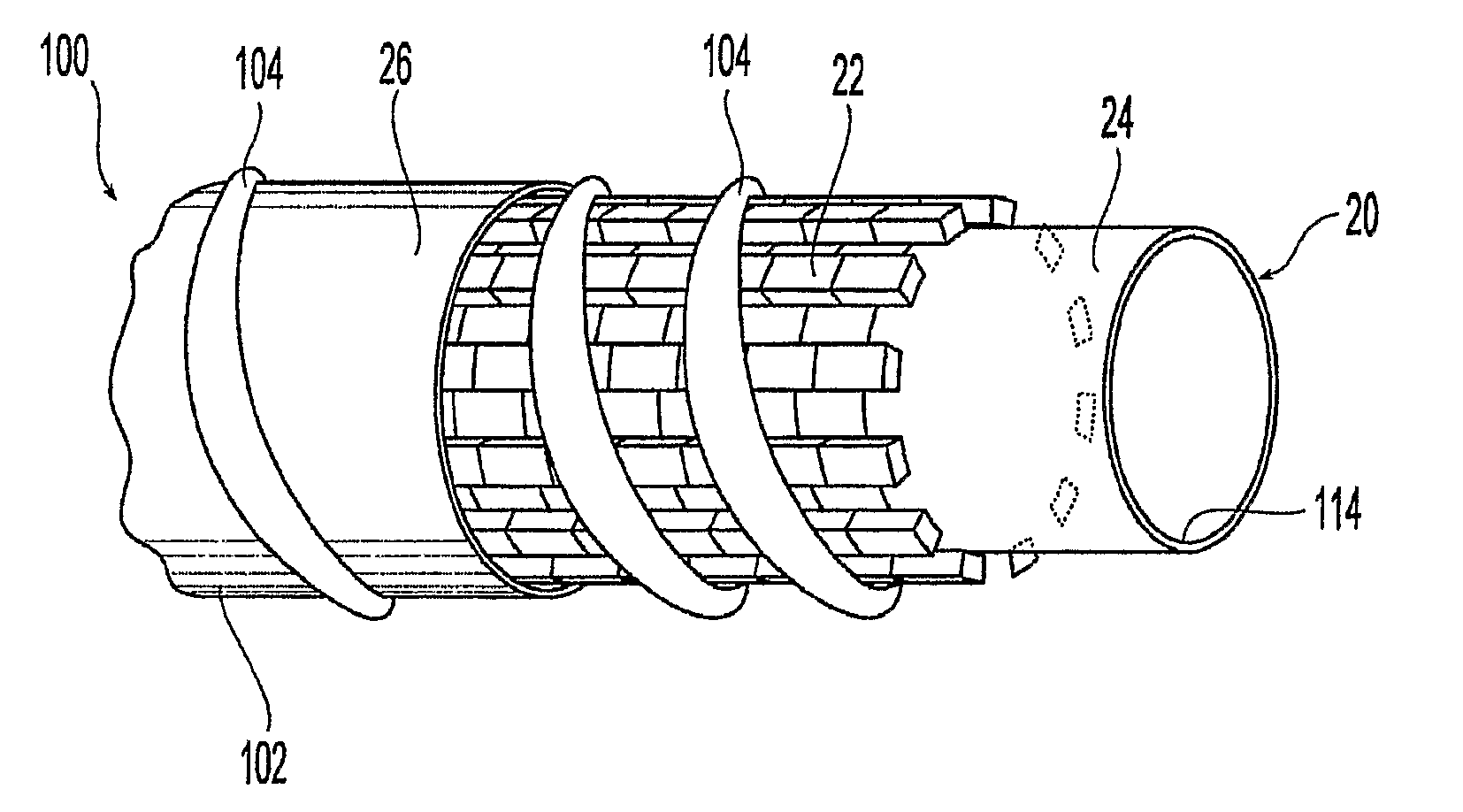
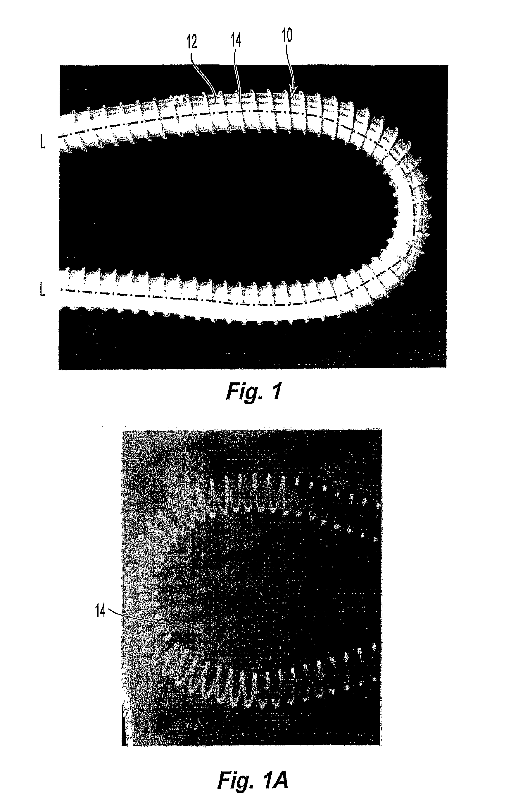
[0033]FIG. 1 shows a preferred embodiment of a medical device implant 10 having an outer surface 12 and an inner surface (not shown). The device 10 is preferably a graft device and its outer surface 12 preferably defines a substantially tubular member about a central axis L-L of the device 10. Preferably, the device 10 defines a substantially circular cross-section perpendicular to the central axis, although other cross-sectional geometries are possible such as, for example, rectangular or oval. The device 10 is preferably configured for migration through a blood vessel to engage, for example, a stenosis. Alternatively, the device 10 can be substantially spherical or any other geometry appropriately dimensioned for implantation and migration in blood vessels or other tissue. Exemplary graft devices 10 include IMPRA CARBOFLO® and CENTERFLEX® by Bard Peripheral Vascular, Inc., Tempe, Ariz.

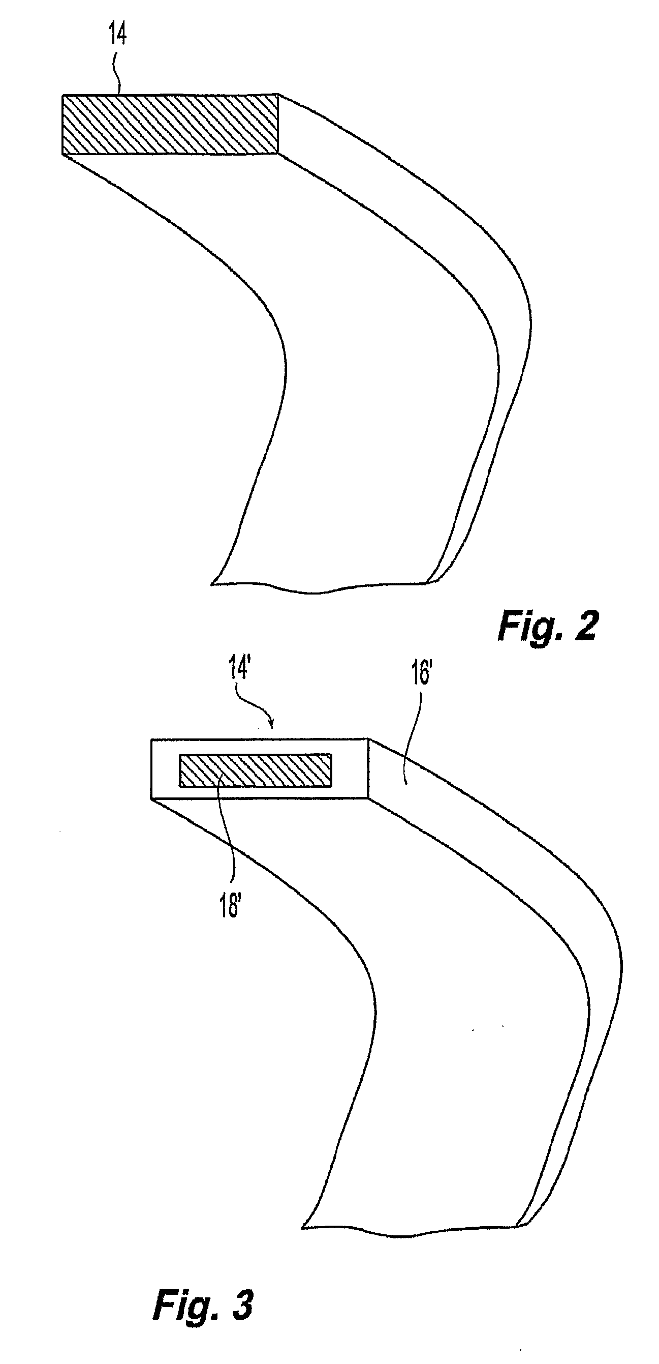
[0034]Disposed or coupled to the outer surface is a beading 14. “Beading” as used herein means a ...


PUM


Abstract

A device and method provides a graft having a layer of synthetic non-metallic material including a first surface and a second surface spaced apart from the first surface. The device further includes a beading coupled to the layer and a radiopaque agent coupled to the beading. Another device and method provides a implantable prosthesis having a stent frame, a first inner layer and a second outer layer defining a central axis. The implantable prosthesis further includes a beading coupled to at least one the layers.

Description

PRIORITY DATA AND INCORPORATION BY REFERENCES[0001]This application claims benefit of priority to U.S. Provisional Patent Application No. 60 / 734,726 filed Nov. 9, 2005 which is incorporated by reference in its entirety.TECHNICAL FIELD[0002]The present invention relates generally to medical devices, and more particularly to a radiopaque beading for implantable devices.BACKGROUND OF THE INVENTION[0003]Unless mentioned specifically, the term radio-opaque and radiopaque have the same meaning. Artificial grafts, stent grafts and related endoluminal devices are currently used by operators to treat tubular body vessels or ducts that become so narrowed (stenosed) that flow of blood or other biological fluids is restricted. Such narrowing (stenosis) occurs, for example, as a result of the disease process known as arteriosclerosis. These products can be used to “prop open” blood vessels, they can also be used to reinforce collapsed or narrowed tubular structures in the respiratory system, the...

Claims


Application Information

Patent Timeline
IPC IPC(8): A61F2/06A61B5/05
CPCA61L31/18
Inventor CASANOVA, R. MICHAELPATHAK, P.
Owner CR BARD INC
Why Eureka
Try Eureka