

Internal combustion engine
- Summary
- Abstract
- Description
- Claims
- Application Information
AI Technical Summary
Benefits of technology
Problems solved by technology
Method used
Image

Examples
Embodiment Construction
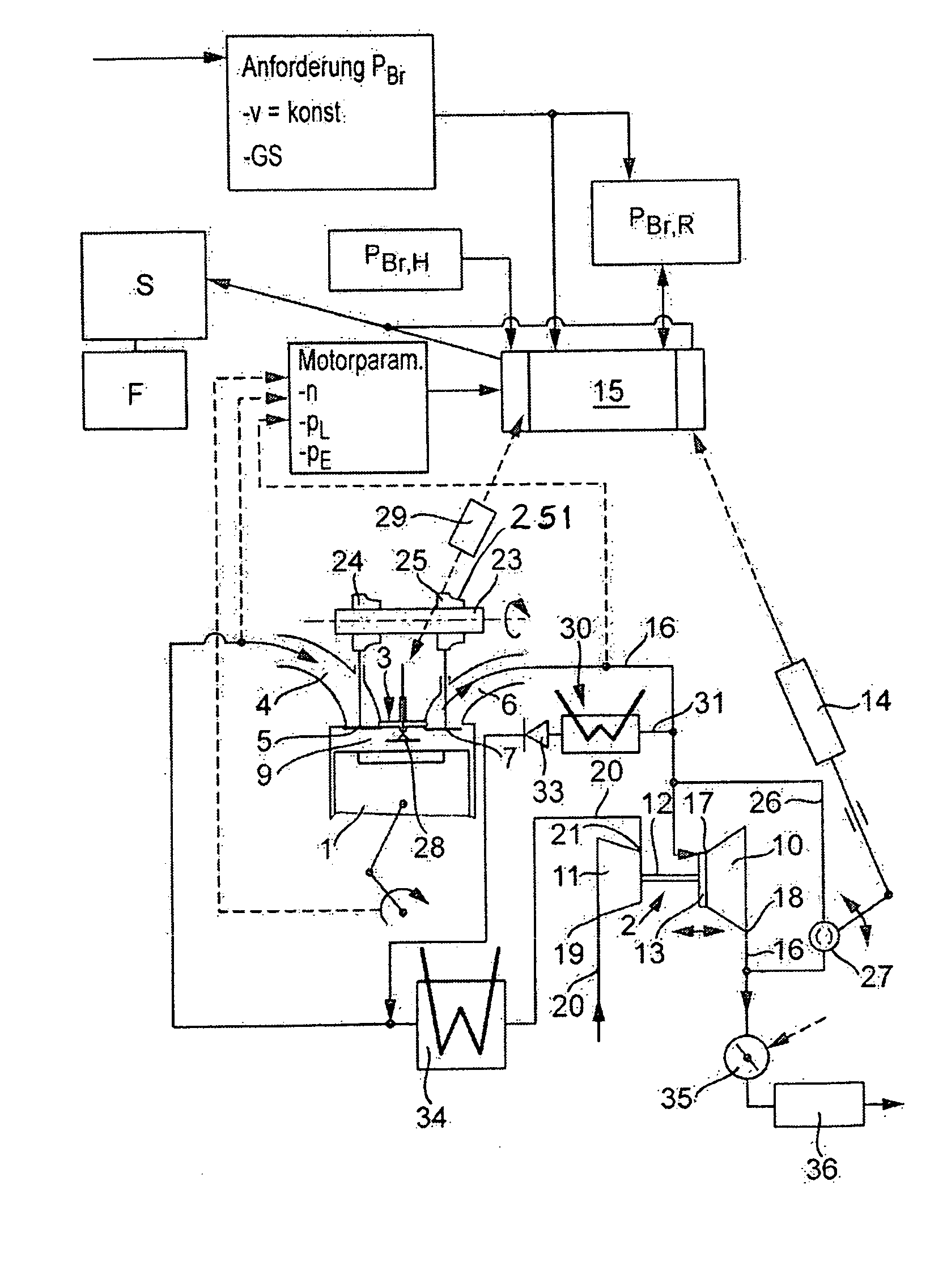
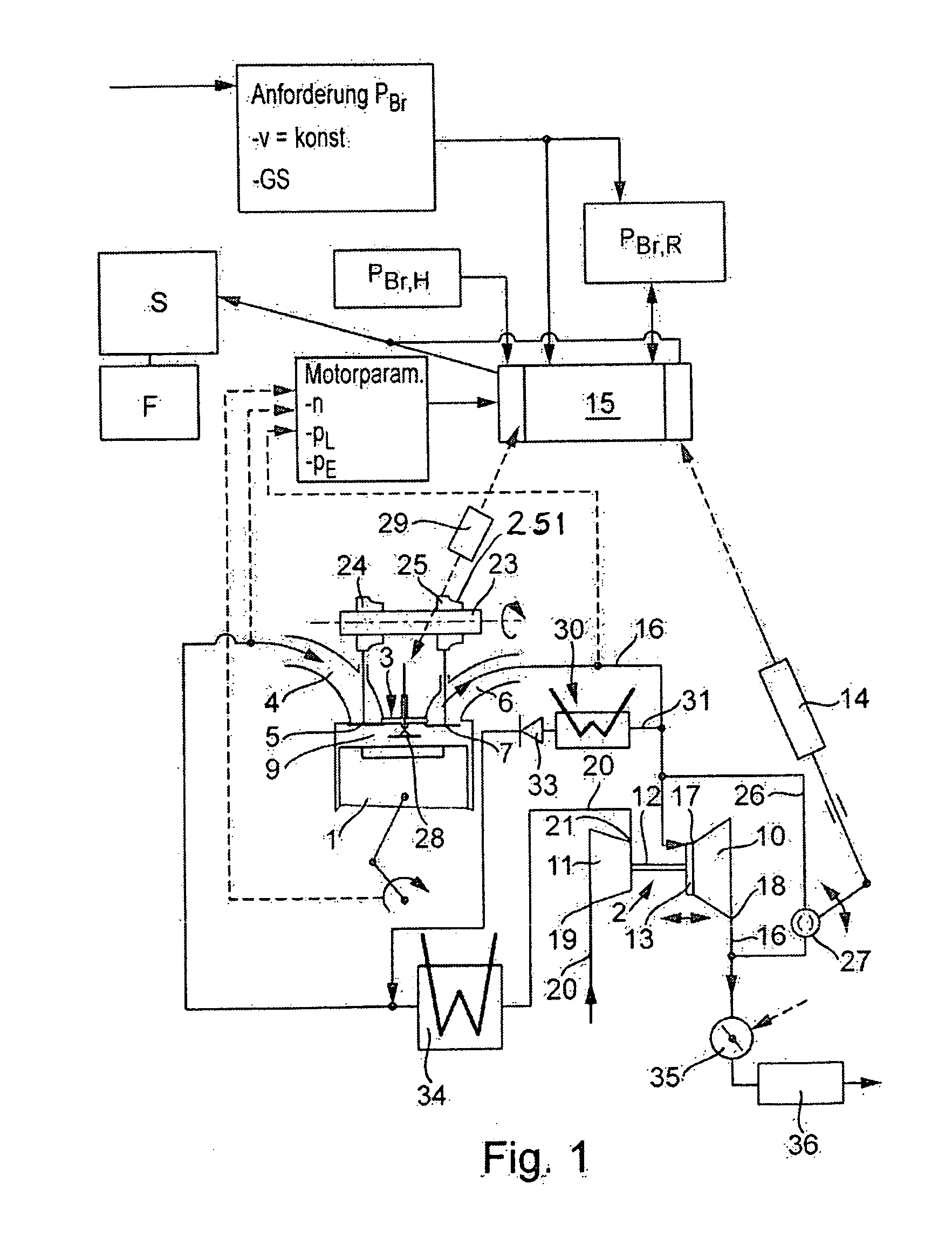
[0017]FIG. 1 shows an internal combustion engine which is for example a diesel engine or a spark ignition engine. The enlarged view indicates a cylinder 1 of the internal combustion engine, the combustion chamber 9 of which is flow-connected to the inlet channel 4 via an inlet valve 5 and to the exhaust manifold 6 via an outlet valve 7. The inlet channel 4 is part of the intake tract 20 of the internal combustion engine, whereas the exhaust manifold 6 is connected to the exhaust line 16 of the internal combustion engine. When the inlet valve 5 is opened, combustion air flows via the inlet channel 4 into the combustion chamber of the cylinder 1; when the outlet valve 7 is opened, the gas located in the combustion chamber is discharged from the combustion chamber into the exhaust train or the exhaust line 16 via the exhaust manifold 6.
[0018]The charge exchange valves 5 and 7 are controlled by a camshaft 23 on which cams 24 and 25 are arranged, of which the cam 24 is associated with th...
PUM
 Abstract
Description
Claims
Application Information