Secondary cell electrode and fabrication method, and secondary cell, complex cell, and vehicle

a technology of secondary cells and electrodes, applied in the field of secondary cells, can solve problems such as the reduction of cell performance such as charge or discharge capacity

Inactive Publication Date: 2009-07-09
NISSAN MOTOR CO LTD
View PDF10 Cites 22 Cited by
  • Summary
  • Abstract
  • Description
  • Claims
  • Application Information

AI Technical Summary

Problems solved by technology

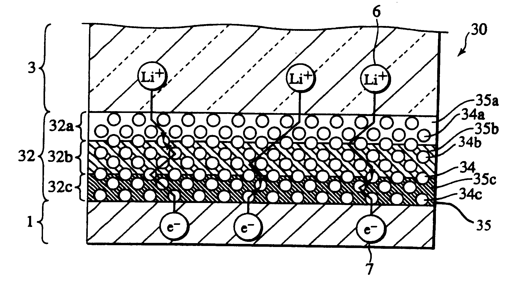
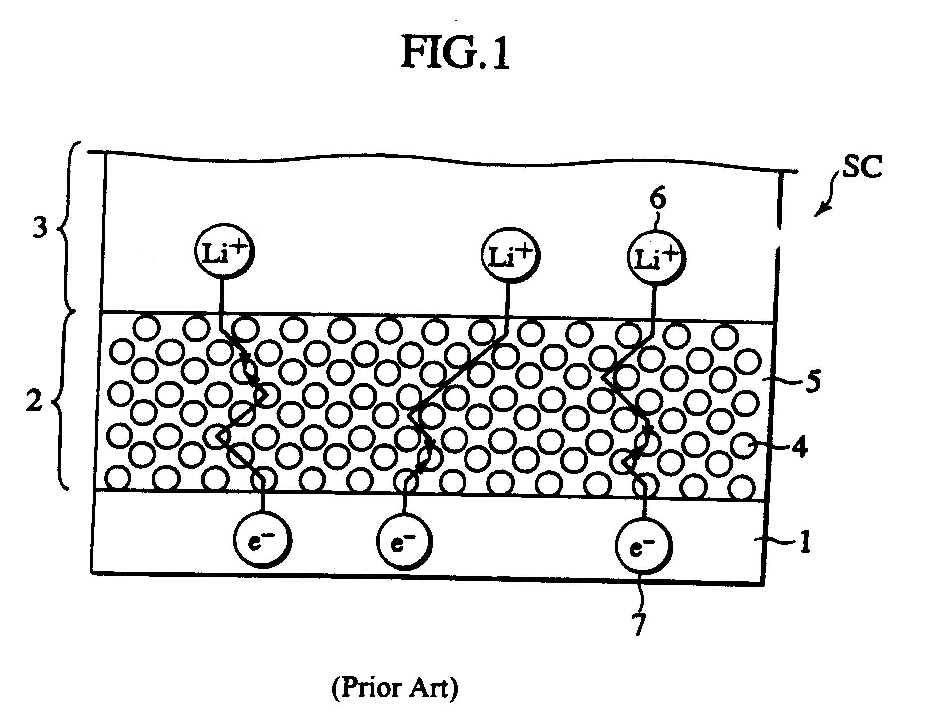
As will be discussed later, such a laminate cell suffers an unfavorable tendency for Li ions to be exhausted in a charge or discharge at a high current rate, resulting in a reduced cell performance such as charge or discharge capacity.

Method used


Image

  • Secondary cell electrode and fabrication method, and secondary cell, complex cell, and vehicle
  • Secondary cell electrode and fabrication method, and secondary cell, complex cell, and vehicle
  • Secondary cell electrode and fabrication method, and secondary cell, complex cell, and vehicle

Examples


first embodiment

3.1 Examples of First Embodiment

[0459]The first embodiment is exemplified below.

3.1.1 Example-1

3.1.1a Preparation of positive electrode ink

[0460]A quantity (90 g in weight) of spinel structure LiMn2O4 (particle size: 0.6 μm in average) as a positive electrode active material, a quantity (5 g in weight) of acetylene black as an electrically conductive material, and a quantity (5 g in weight) of polyvinylidene fluoride as a binder were mixed, and as a solvent to this mixture a quantity (300 g in weight) of acetonitrile was admixed, thereby preparing a kind of slurry as a positive electrode ink-1. The positive electrode ink-1 had a viscosity of 3 cP at a temperature of 25° C.

[0461]Next, the positive electrode active material, electrically conductive material, and binder were mixed in the same amounts as those of the positive electrode ink-1, and as a solvent to this mixture a quantity (500 g in weight) of acetonitrile was admixed, thereby preparing another kind of slurry as a positive ...

second embodiment

3.2 Examples of Second Embodiment

[0489]The second embodiment is exemplified below.

3.2.1 Example-2

3.2.1a Preparation of Positive Electrode Ink

[0490]A quantity (90 g in weight) of spinel structure LiMn2O4 (particle size: 0.6 μm in average) as a positive electrode active material, a quantity (5 g in weight) of acetylene black as an electrically conductive material, a quantity (5 g in weight) of polyvinylidene fluoride as a binder, a quantity (40 g in weight) of LiBETl as an electrolyte salt, a quantity (40 g in weight) of macromer of ethylene oxide and propylene oxide as an electrolyte polymer synthesized in accordance with a method described in Japanese Patent Application Laid-Open Publication No. 2002-110239, and a quantity (0.1 mass % of the electrolyte polymer) of benzyldimethyl-ketal as a photochemical polymerization initiator were mixed, and as a solvent to this mixture a quantity (820 g in weight) of acetonitrile was admixed, thereby preparing a kind of slurry as a positive elec...


PUM

PropertyMeasurementUnit
thicknessaaaaaaaaaa
thicknessaaaaaaaaaa
thicknessaaaaaaaaaa

Abstract

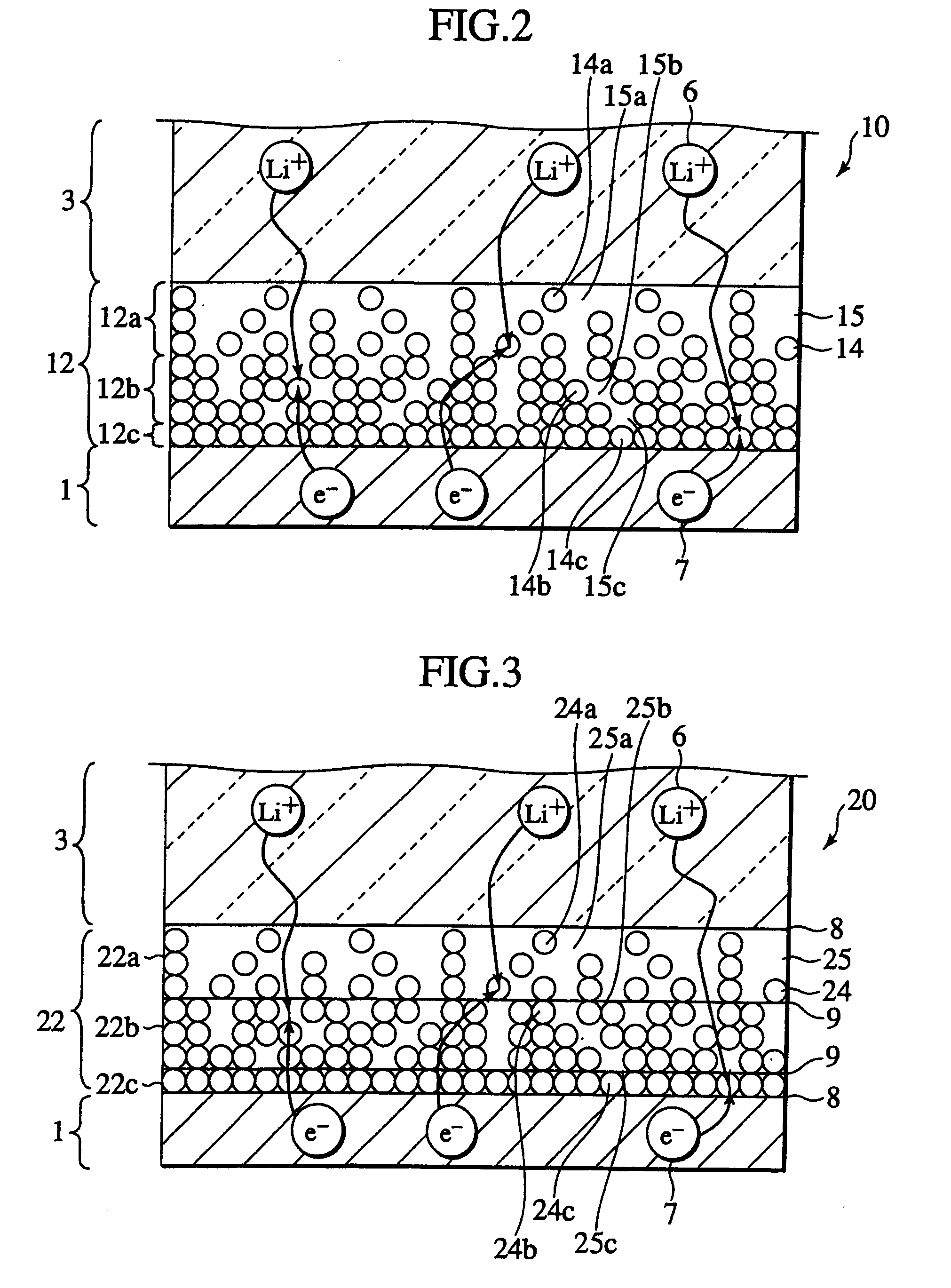
In a nonaqueous electrolyte cell-oriented electrode (10), an electrode active material layer (12) formed on a collector (1) has a density gradient developed with a gradient of a varied concentration of a solid along a thickness from a surface of the electrode active material layer (12) toward the collector (1), and in a gel electrolyte cell-oriented electrode (30), an electrode active material layer (32) formed on a collector (1) has a density gradient developed with (a) gradient(s) of (a) varied concentration(s) of one or both of an electrolyte salt and a film forming material along a thickness from a surface of the electrode active material layer (32) toward the collector (1).

Description

[0001]The present application is a divisional of U.S. application Ser. No. 10 / 565,171, filed Jan. 19, 2006, which is the national stage entry of PCT / JP2004 / 011021, filed Jul. 27, 2004, which in turn claims benefit of priority to Japanese application Nos. 2003-283974 and 2003-283975, both filed Jul. 31, 2003, the entire contents of which are incorporated herein by reference.TECHNICAL FIELD[0002]The present invention relates to a secondary cell electrode, and particularly, to a nonaqueous electrolyte electrode and a gel electrolyte electrode, and further to a fabrication method of the same, as well as to a secondary cell employing the secondary cell electrode, a complex cell employing the secondary cell, and a vehicle employing the secondary cell or the complex cell.BACKGROUND ART[0003]Recent years have observed, on the background with a rising trend for environmental protection, demands for a promoted introduction of an electric vehicle (EV), a hybrid vehicle (HEV), and a fuel cell p...

Claims


Application Information

Patent Timeline
Patent Type & Authority Applications(United States)
IPC IPC(8): C25B11/00C25D21/14H01M4/02H01M4/04H01M4/08H01M4/36H01M6/18H01M8/02H01M8/10H01M10/0525H01M10/36H01M50/543
CPCH01M2/021H01M4/02H01M4/0404Y02E60/122H01M10/0525H01M2300/0022H01M2300/0085H01M4/366Y02E60/10H01M50/543H01M4/08H01M4/04
Inventor NAGAYAMA, MORISAITO, TAKAMISTUSHIMAMURA, OSAMU
Owner NISSAN MOTOR CO LTD
Why Eureka
Try Eureka