Atmospheric pressure plasma, generating method, plasma processing method and component mounting method using same, and device using these methods

a technology of atmospheric pressure and plasma, which is applied in the field of atmospheric pressure plasma, generating method, plasma processing method and component mounting method using same, and device using these methods, can solve the problem that the method and device need only small electric power, and achieve the effect of high versatility and high productivity of the flat panel display

Active Publication Date: 2009-07-23
FUJI CORP
View PDF10 Cites 19 Cited by
  • Summary
  • Abstract
  • Description
  • Claims
  • Application Information

AI Technical Summary

Benefits of technology

[0023]The present invention has been completed based on the fact found through the diligent study about the method for generating an atmospheric pressure plasma by the present inventors, wherein when an inert gas was supplied toward a plasma ejected from a reaction space to collide the plasma with the inert gas, the supplied inert gas was made into a plasma with an avalanche multiplication and the plasma largely expands. Therefore, according to the method and device for generating an atmospheric pressure plasma of the present invention, the first inert gas is made into a plasma in the reaction space by applying the high-frequency electric field and is ejected as the primary plasma. The primary plasma collides into the mixed gas area of the second inert gas and the reactive gas so that the second inert gas with which the primary plasma collides is made into a plasma with the avalanche multiplication and expands to the whole mixed gas area. The reactive gas is made into a plasma by radicals of the second inert gas which has been made into the plasma, and hence the plasma expands in a wide range in a perspective direction and planar direction with respect to the reaction space and carries out a plasma processing. Also, the method and device need only small electric power because the high-frequency electric field is applied to only the reaction space where the primary plasma is generated. Since the input power is small, the temperature of the generated secondary plasma is low, so that there is an effect that it becomes possible to easily carry out the plasma processing on a substrate with low heat resistance such as a substrate on which a component with low heat resistance has been mounted and the like.
[0043]If the moving means is provided with a robot device and the plasma head is mounted on a movable head which is movable in X, Y, and Z directions of the robot device, the component to-be-bonded portion is appropriately and efficiently subjected to the plasma processing by fixing the substrate in a predetermined position and moving the plasma head along the component to-be-bonded portion. Accordingly, it is possible to carry out the plasma processing on an arbitrary substrate with high versatility.

Problems solved by technology

Also, the method and device need only small electric power because the high-frequency electric field is applied to only the reaction space where the primary plasma is generated.

Method used


Image

  • Atmospheric pressure plasma, generating method, plasma processing method and component mounting method using same, and device using these methods
  • Atmospheric pressure plasma, generating method, plasma processing method and component mounting method using same, and device using these methods
  • Atmospheric pressure plasma, generating method, plasma processing method and component mounting method using same, and device using these methods

Examples


first embodiment

[0072]A first embodiment of an atmospheric pressure plasma generating device according to the present invention will now be described with reference to FIGS. 1 to 4B.

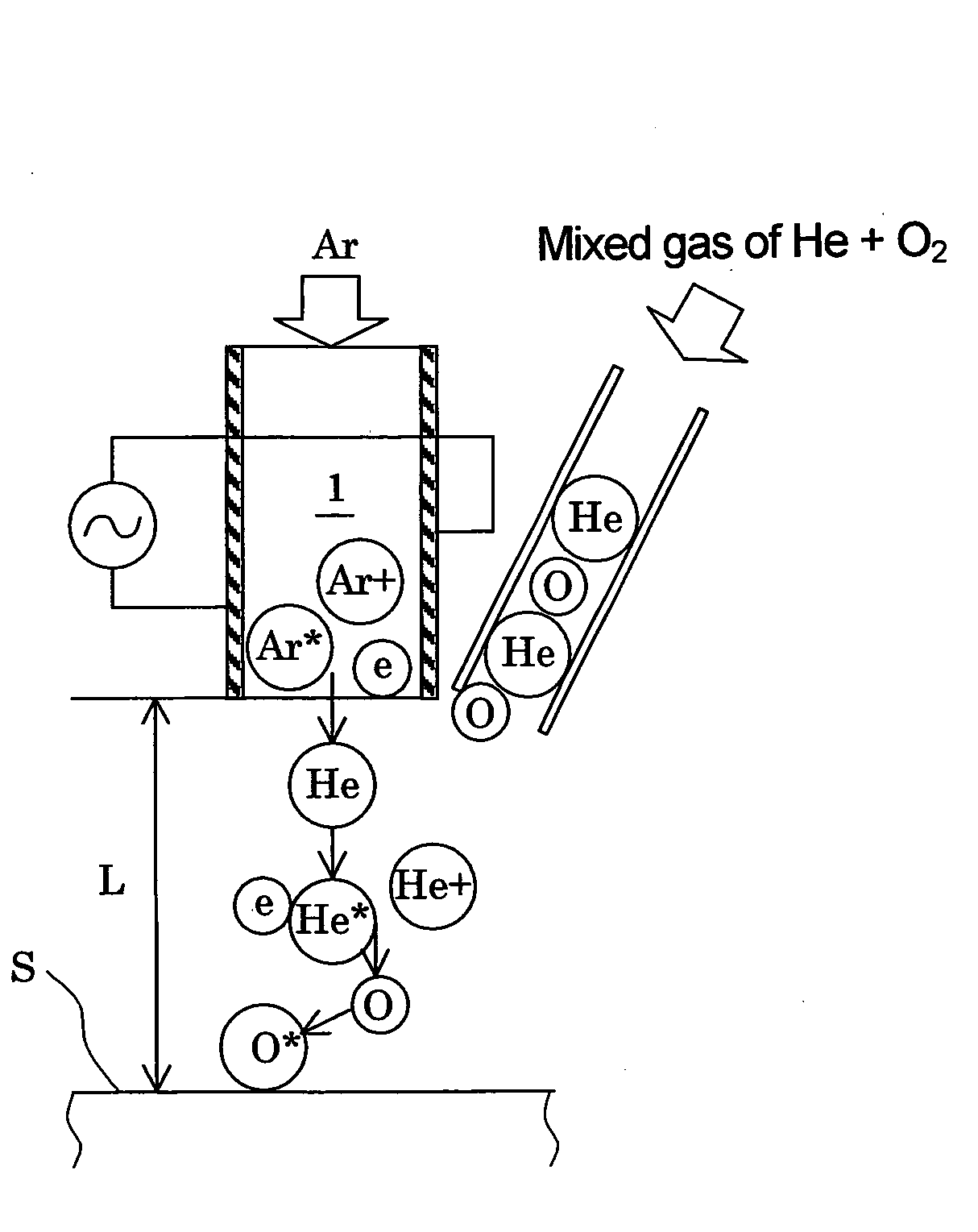
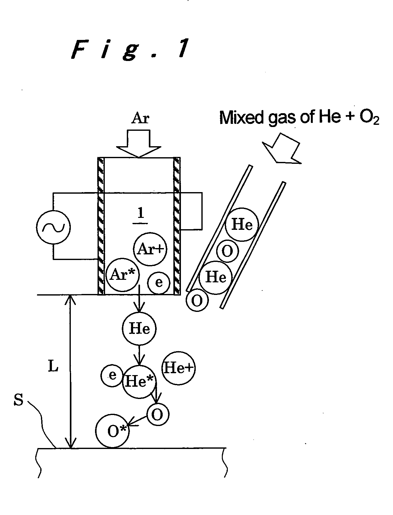
[0073]First, the principle of a method for generating an atmospheric pressure plasma according to the present invention will be described with reference to FIG. 1. FIG. 1 shows an example in which argon is used as a first inert gas, helium is used as a second inert gas, oxygen is used as a reactive gas, and a mixed gas of the second inert gas and the oxygen is supplied. Since argon is supplied and a high-frequency electric field is applied to a reaction space 1, argon atoms (Ar) in the reaction space 1 are excited or ionized by electrons (e) in a discharge plasma and become argon radicals (Ar*), argon ions (Ar+), and electrons (e). The argon radicals (Ar*) in a metastable state with high energy react with the same or different kinds of atoms in the vicinity thereof for the purpose of returning to a stable state by makin...

second embodiment

[0085]A second embodiment of the atmospheric pressure plasma generating device according to the present invention will now be described with reference to FIGS. 5A to 6B. In the description described below, the same reference numbers will refer to the same components as the foregoing embodiment and the description thereof will be omitted. Only differences will be mainly described.

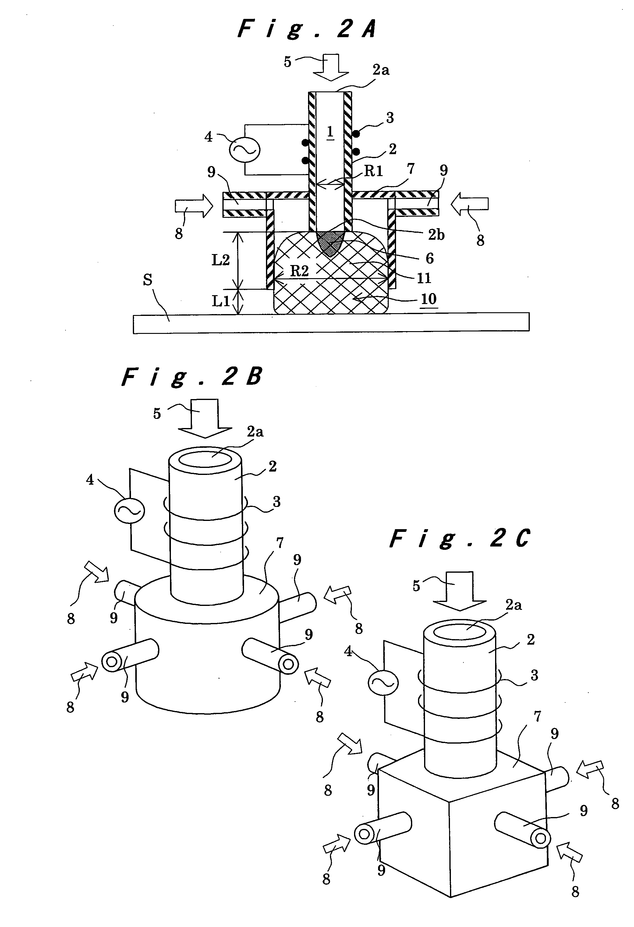
[0086]The foregoing first embodiment disclosed an example in which the cylindrical reaction vessel 2 was used, the antenna 3 disposed on the periphery thereof applied the high-frequency electric field to the reaction vessel 1, and the mixed gas vessel 7 was disposed on the periphery of the lower end 2b of the reaction vessel 2. The second embodiment, as shown in FIGS. 5A and 5B, has a rectangular tube-shaped reaction vessel 14 with a slender rectangle in cross section serving as an plasma generating section, and a pair of electrodes 15a and 15b is disposed in its long walls opposite to each other. The whole ...

third embodiment

[0089]A third embodiment of the atmospheric pressure plasma generating device according to the present invention will now be described with reference to FIG. 7.

[0090]In the foregoing first and second embodiments, the mixed gas vessel 7 and 16 for supplying the mixed gas 8 was disposed on the periphery of the lower end of the reaction vessel 2 and 14. In this embodiment, as shown in FIG. 7, an inert gas vessel 18 for supplying a second inert gas 12 is disposed on the periphery or on both sides of the reaction vessel 2 and 14. A reactive gas vessel 19 for supplying a reactive gas 13 is disposed on the periphery or on both sides of the inert gas vessel 18, and a mixed gas area 10 is formed in the inside thereof by downwardly extending outside walls of the reactive gas vessel 19.

[0091]According to this structure, since a primary plasma 6 ejected from the reaction vessel 2 and 14 first collides with an atmosphere of only the second inert gas 12 supplied from the inert gas vessel 18, the ...


PUM

PropertyMeasurementUnit
pressureaaaaaaaaaa
sizeaaaaaaaaaa
sizeaaaaaaaaaa

Abstract

A first inert gas (5) is supplied into a reaction space (1) and a high-frequency power supply (4) applies a high-frequency electric field so that a primary plasma (6) composed of the first inert gas which has been made into the plasma is ejected from the reaction space. A mixed gas area (10) in which a mixed gas (8) having a second inert gas (12) as a main ingredient and a proper amount of a reactive gas (13) mixed is formed. The primary plasma collides into the mixed gas area to generate a secondary plasma (11) composed of the mixed gas which has been made into the plasma, and the secondary plasma is sprayed on a processed object (S) to carry out a plasma processing. Accordingly, the plasma processing is carried out in a wide range by an atmospheric pressure plasma generated by a small input power.

Description

TECHNICAL FIELD[0001]The present invention relates to a method for generating an atmospheric pressure plasma which carries out a plasma processing in a wide range with small input power, a processing method and a component mounting method by the generated atmospheric pressure plasma, and a device using these methods.BACKGROUND ART[0002]Conventionally, there is known an atmospheric pressure plasma generating device which makes an inert gas into a plasma in the vicinity of atmospheric pressures (in a range of 500 to 1500 mmHg in terms of pressure) and makes a reactive gas into a plasma by the generated radicals of the inert gas to carry out a plasma processing such as surface reforming, etching, and deposition. In such an atmospheric pressure plasma generating device, the inert gas and the reactive gas mixed at a predetermined ratio in advance are provided to one end of a cylindrical reaction vessel. Applying a high-frequency electric field to the reaction vessel makes the mixed gas i...

Claims


Application Information

Patent Timeline
Patent Type & Authority Applications(United States)
IPC IPC(8): H05H1/24
CPCH01J37/32366H05H1/24H01J37/32825H05H1/30H05H1/42H05H1/46H05H1/4652
Inventor TSUJI, HIROYUKIINOUE, KAZUHIRO
Owner FUJI CORP
Why Eureka
Try Eureka