Elecrically conductive adhesive

Active Publication Date: 2009-07-23
DU PONT CHINA LTD
View PDF5 Cites 28 Cited by
  • Summary
  • Abstract
  • Description
  • Claims
  • Application Information

AI Technical Summary

Benefits of technology

[0009]The present invention provides an electrically conductive adhesive that improves adhesive strength, h

Problems solved by technology

Also, the detrimental effect of heat possessed by molten solder on electronic components that lack heat resistance may also become a problem.
However, electrically conductive adhesives composed of conventional thermoplastic organic binder resins still lack adhesiveness to many inorganic substrates or electrodes.
In addition, since electric components or electric devices mounted on a substrate with an electrically conductive adhesive have low heat resistance, there is the problem of de

Method used


Image

  • Elecrically conductive adhesive
  • Elecrically conductive adhesive
  • Elecrically conductive adhesive

Examples


examples

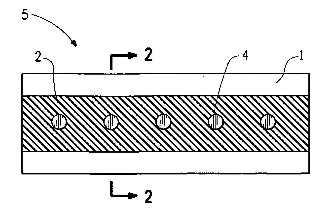
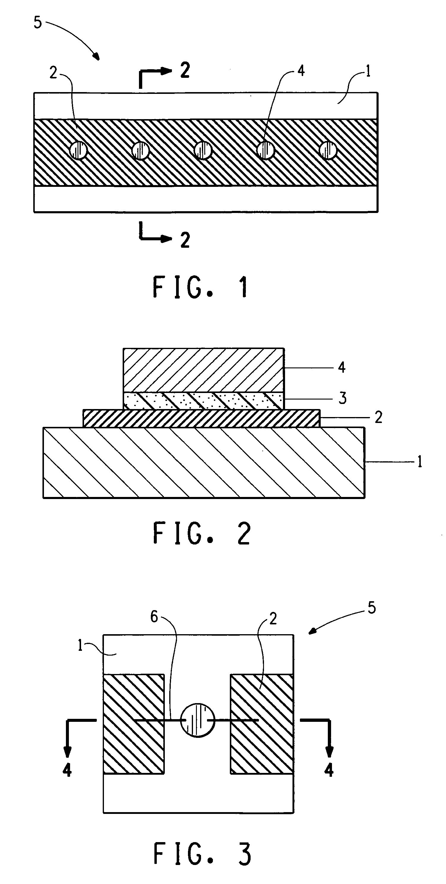
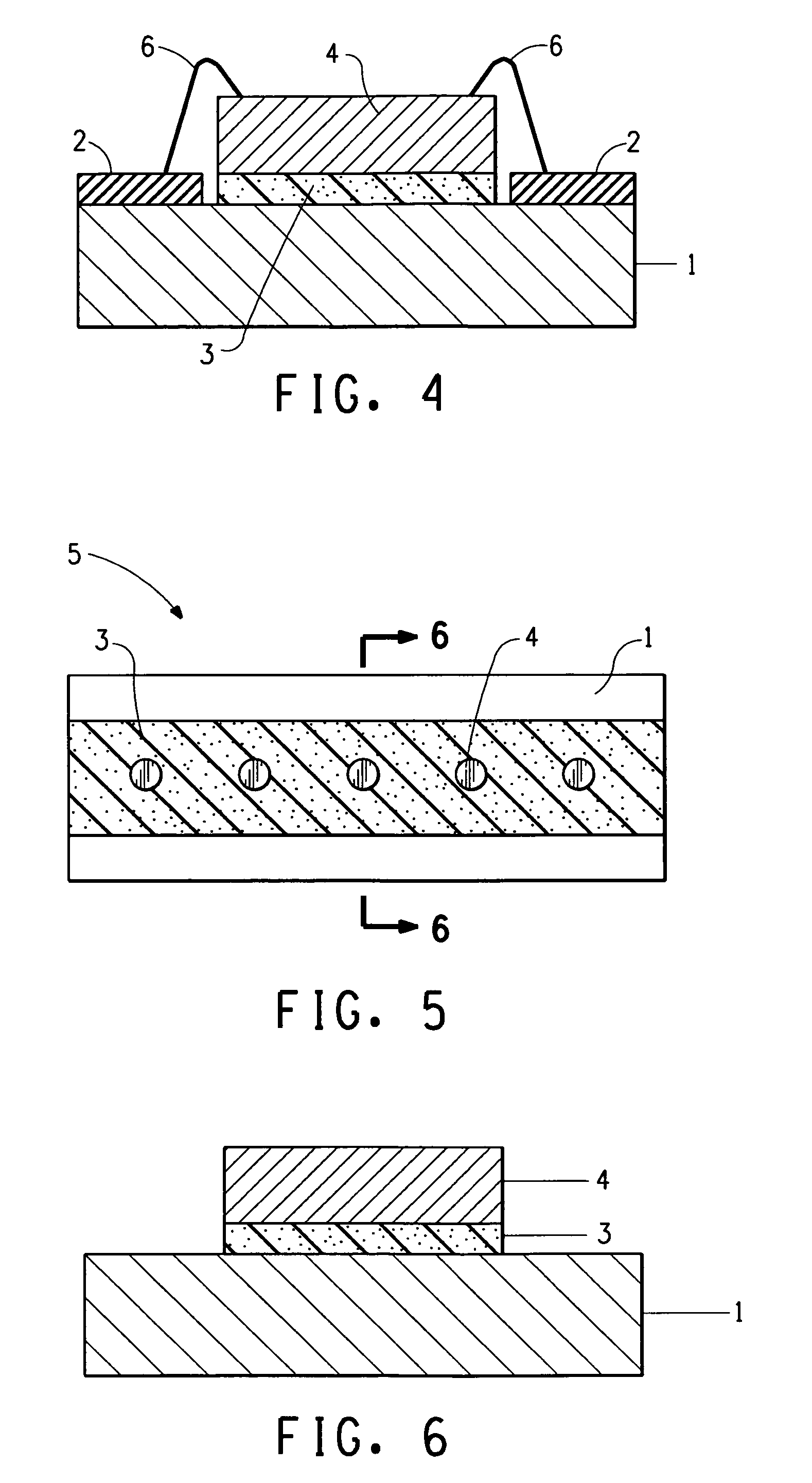
[0037]The following provides an explanation of specific examples of the electrically conductive adhesive of the present invention. Electrically conductive adhesives were fabricated having different composite ratios of, electrically conductive powder, heat-curable silicone resin and solvent. The electrically conductive adhesives having different composite ratios are respectively designated as Examples 1 to 20 (see Table 1). The details of each composition are as described below.

[0038]Electrically Conductive Powder[0039]Silver powder having a mean particle diameter of 1 μm (#11000-10, Ferro Co., Ltd.)[0040]Silver powder having a mean particle diameter of 0.3 μm (#11000-25, Ferro Co., Ltd.)[0041]Silver powder having a mean particle diameter of 5 μm (SF26, Ferro Co., Ltd.)[0042]Colloidal silver having a mean particle diameter of 10 nm and silver content of 80% (TB-A02, Dowa Electronics Co., Ltd.) Solvent (Texanol, Wako Pure Chemical Industries, Ltd.)

[0043]Heat-Curable Silicone Resin

[004...


PUM

PropertyMeasurementUnit
Angleaaaaaaaaaa
Percent by massaaaaaaaaaa

Abstract

Disclosed is an electrically conductive adhesive that includes an electrically conductive powder, a heat-curable silicone resin, and a solvent.

Description

BACKGROUND OF THE INVENTION[0001]1. Field of the Invention[0002]The present invention relates to an electrically conductive adhesive in an electric circuit board. The adhesive, which is basically made from the heat-curable silicone resin, shows excellent adhesiveness to an inorganic substrate and excellent thermal conductivity. The conductive adhesive is useful as an electronic component.[0003]2. Technical Background[0004]Solder provided with both electrical conductivity and adhesiveness has been conventionally used to adhere electronic components to a substrate or electric circuit when mounting on an electric circuit board. In recent years, however, there has been a tendency to avoid the use of solder containing lead. Also, the detrimental effect of heat possessed by molten solder on electronic components that lack heat resistance may also become a problem. Therefore, electrically conductive adhesives consisting mainly of a resin and a metal powder have come to be used in recent ye...

Claims


Application Information

Patent Timeline
IPC IPC(8): B32B7/12H01B1/00H01B1/04H01B1/02H01B1/12
CPCC08K3/08C09J9/02C09J183/04C09J2203/326Y10T428/2852H05K3/321H05K2201/0162Y10T428/2848C09J2483/00H01L2224/45144H01L2224/48091H01L2224/73265H01L2224/92247H01L2924/00014H01L2924/00
Inventor INABA, AKIRA
Owner DU PONT CHINA LTD
Why Eureka
Try Eureka