Oct optical probe and optical tomography imaging apparatus

a technology of optical tomography and optical probe, which is applied in the field of optical tomography imaging apparatus, can solve the problems of difficult size reduction, high cost of mems motor, and degraded accuracy of measurement, and achieve the effect of eliminating costs and avoiding problems

Inactive Publication Date: 2009-08-06
FUJIFILM CORP +1
View PDF5 Cites 149 Cited by
  • Summary
  • Abstract
  • Description
  • Claims
  • Application Information

AI Technical Summary

Benefits of technology

[0017]In view of the above-described circumstances, the present invention is directed to providing an OCT optical probe and an optical tomography imaging apparatus using the OCT optical probe, that can inexpensively and safely eliminate the prior art problem of degradation in measurement accuracy due to optical insertion loss and optical reflection loss caused at optical coupling at a rotary joint disposed between an optical fiber at a distal end portion side and an optical fiber at a proximal end portion.

Problems solved by technology

Therefore, accuracy of the measurement may be degraded due to optical insertion loss and optical reflection loss caused, for example, by positional offset between optical axes of these fibers.
However, the MEMS motor is expensive and size reduction thereof is difficult, and therefore it may be difficult to insert the MEMS motor into the inner diameter of the forceps channel of the endoscope.
In addition, a drive cable for the MEMS motor may block the light emitted from the distal end portion and affect image acquisition.

Method used


Image

  • Oct optical probe and optical tomography imaging apparatus
  • Oct optical probe and optical tomography imaging apparatus
  • Oct optical probe and optical tomography imaging apparatus

Examples


first embodiment

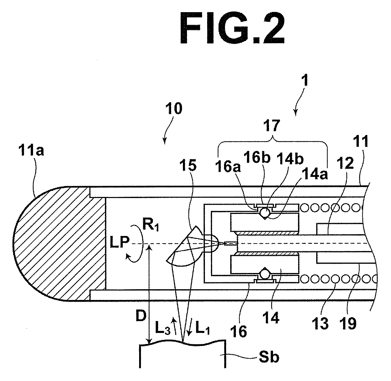
[0067]In the first embodiment, the sheath 11 is fitted in and fixed to a housing 25, and a shaft bearing 22 is disposed in the housing 25. The flexible shaft 13 is fixed to a shaft supporting member 21, and the shaft supporting member 21 is held to be rotatable relative to the housing 25 via the shaft bearing 22. The optical fiber 12 is fixed to the housing 25. A driven gear wheel 23 is fixed to the outer circumference of the shaft supporting member 21, and a driving gear wheel 24 is disposed to mesh with the driven gear wheel 23. The driving gear wheel 24 is fixed to the output shaft of the motor 26, which is disposed in the housing 25. The motor 26 includes an encoder 27 for detecting a rotational angle. A control signal MC fed to the motor 26 and a rotation signal RS fed from the encoder 27 are transmitted via a control cable (not shown). Specifically, the rotation signal RS includes a rotation clock signal RCLK, which is generated for each rotation of the motor 26, and a rotatio...

second embodiment

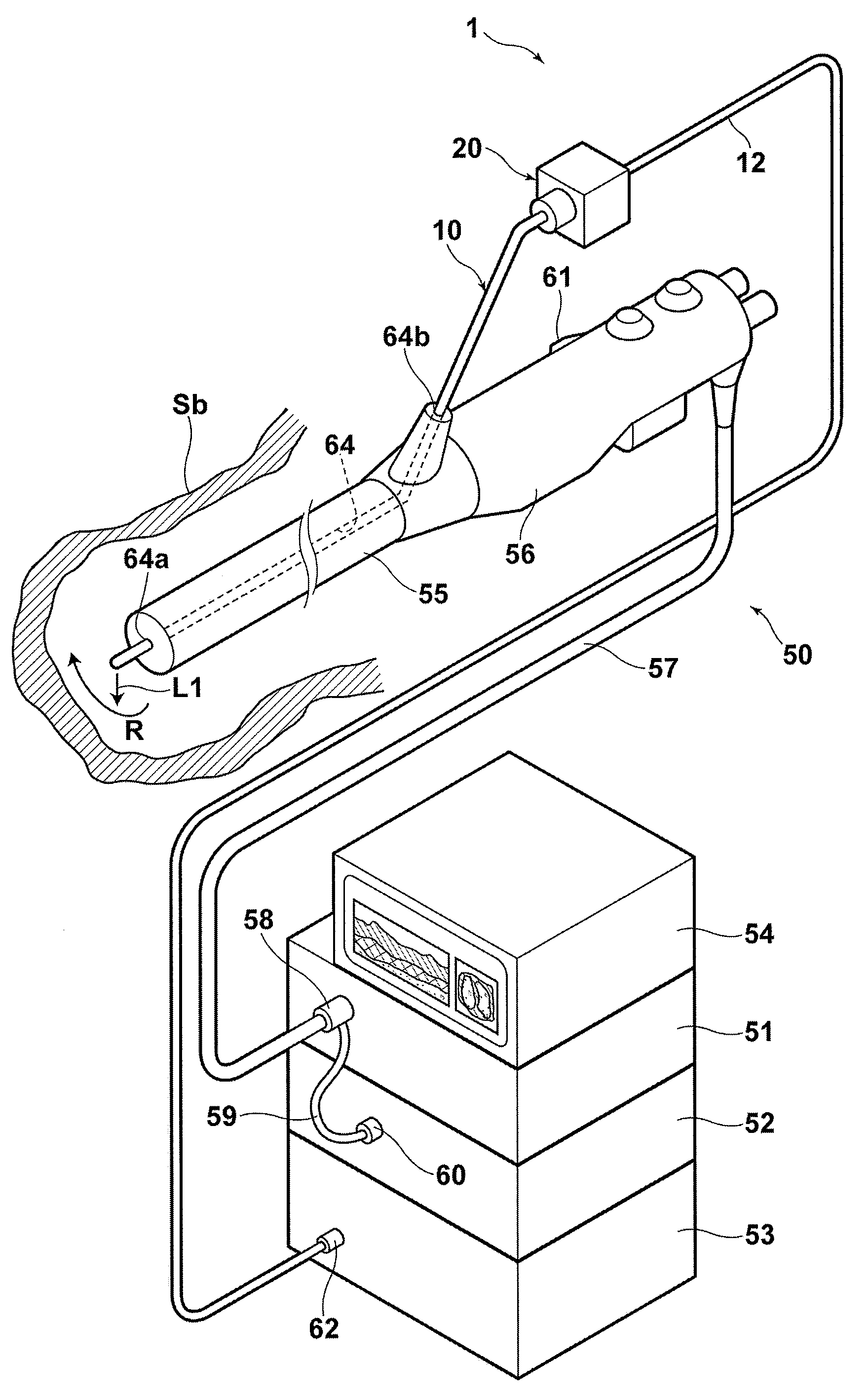
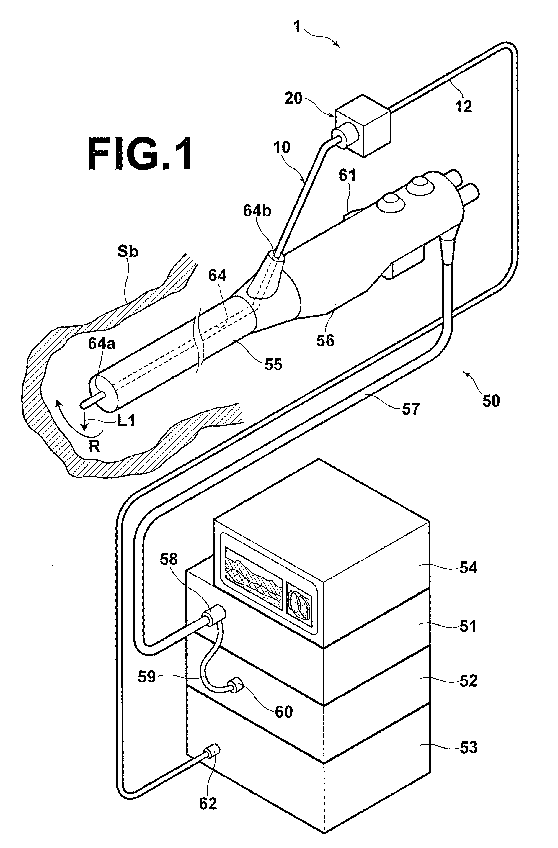
[0071]In the second embodiment shown in FIG. 8, a permanent magnet 18 is disposed at the outer circumference of the flexible shaft 13, and an electric magnet 68 is disposed at the outer circumference of the forceps channel 64 of the insert portion 55 of the endoscope 50. Further, a magnetic sensor (not shown) may be disposed at the outer circumference of the permanent magnet 18 for detecting the rotational angle of the optical fiber 12. A control signal MC fed to the electric magnet 68 and a rotation signal RS fed from the magnetic sensor are transmitted via a control cable (not shown). Specifically, the rotation signal RS include a rotation clock signal RCLK, which is generated for each rotation of the flexible shaft 13, and a rotational angle signal Rpos.

[0072]Now, operation of the second embodiment is described. When the electric magnet 68 is excited, the electric magnet 68 and the permanent magnet 18 interact with each other to establish a relationship of a stator and a rotor of...


PUM


Abstract

An OCT optical probe to be inserted into a subject includes: a cylindrical sheath to be inserted into a subject; an optical fiber disposed in the internal space of the sheath; a rotatably-supporting portion fixed to the optical fiber in the vicinity of a distal end of the optical fiber; a distal optical system to deflect light emitted from the distal end of the optical fiber toward the subject; a holding portion to hold the distal optical system such that the optical system is rotatably supported by the rotatably-supporting portion; and a flexible shaft covering the optical fiber in the internal space, wherein the holding portion is fixed to a distal end of the flexible shaft. Using the OCT optical probe of the invention, the problem of degradation of measurement accuracy due to optical insertion loss and optical reflection loss at a rotary joint can be eliminated inexpensively and safely.

Description

BACKGROUND OF THE INVENTION[0001]1. Field of the Invention[0002]The present invention relates to an OCT optical probe and an optical tomography imaging apparatus, and particularly to an OCT optical probe having a function of scanning with light in a circumferential direction with respect to the long axis of the OCT optical probe, and an optical tomography imaging apparatus that acquires an optical tomographic image of a subject to be measured through OCT (Optical Coherence Tomography) measurement using the OCT optical probe.[0003]2. Description of the Related Art[0004]As a method for acquiring a tomographic image of a subject to be measured, such as a body tissue, a method using OCT measurement to acquire a tomographic image has been proposed. An OCT measurement system is one of optical interferometers. In the OCT measurement, low-coherent light emitted from a light source is divided into measurement light and reference light. The measurement light is applied to a subject to be meas...

Claims


Application Information

Patent Timeline
Patent Type & Authority Applications(United States)
IPC IPC(8): A61B6/02A61B1/06A61B6/00
CPCA61B5/6852A61B5/0066
Inventor NAKABAYASHI, KOKITOIDA, MASAHIROKATO, KIICHIKOROGI, YUTAKAMASUDA, TADASHI
Owner FUJIFILM CORP
Why Eureka
Try Eureka