Fuel Cell Employing Hydrated Non-Perfluorinated Hydrocarbon Ion Exchange Membrane

a technology of hydrocarbon ion exchange membrane and fuel cell, which is applied in the direction of fuel cell details, cell components, electrochemical generators, etc., can solve the problems of reducing fuel cell performance, reducing fuel cell efficiency, and high cost of membranes, so as to improve the tolerance to carbon monoxide, improve durability, and reduce the cost

Inactive Publication Date: 2009-08-13
AUDI AG
View PDF9 Cites 5 Cited by
  • Summary
  • Abstract
  • Description
  • Claims
  • Application Information

AI Technical Summary

Benefits of technology

[0005]Aspects of the invention include: lower cost proton exchange membranes for fuel cells; proton exchange membranes for fuel cells with improved durability and improved tolerance to carbon monoxide; and low cost, highly durable proton exchange membranes for fuel cells which does not require expensive power plant components that are difficult to control.

Problems solved by technology

However, these membranes are expensive and are prone to degradation due to peroxide formation and its subsequent decomposition products resulting from oxygen solubility.
In addition, these membranes allow some H2 to cross over to the cathode, which has a negative effect on fuel cell efficiency.
Some of the CO attaches to the platinum of the anode catalyst which inhibits the ability of the platinum catalyst sites to oxidize hydrogen which in turn reduces fuel cell performance.
However, the improved performance is short-lived because the ruthenium in the anode is unstable and tends to migrate through the membrane until it is deposited on the cathode.
Ruthenium on the cathode inhibits the cathode reaction, resulting in reduced fuel cell performance.

Method used


Image

  • Fuel Cell Employing Hydrated Non-Perfluorinated Hydrocarbon Ion Exchange Membrane
  • Fuel Cell Employing Hydrated Non-Perfluorinated Hydrocarbon Ion Exchange Membrane

Examples


Embodiment Construction

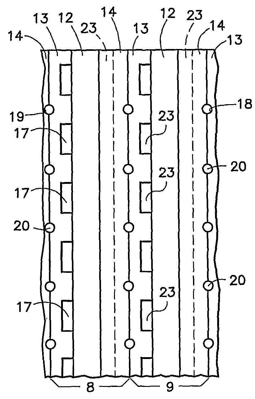
[0021]Referring to FIG. 1, portions of a pair of fuel cells 8, 9 are illustrated. Each fuel cell has a unitized electrode assembly 12, a porous, hydrophilic fuel reactant gas flow field plate 13 and a porous, hydrophilic oxidant reactant gas flow field plate 14. The fuel reactant gas flow field plates 13 includes fuel flow channels 17 and grooves 18 which, with grooves 19 in the oxidant reactant gas flow field plates 14, form channels 20 for liquid water that hydrates the membrane and for removal of product water from the cathodes. The oxidant reactant gas flow field plates 14 have oxidant reactant gas flow field channels 23.

[0022]The channels 20 may be of large cross-section, sufficient to carry enough water for convectively cooling the fuel cells by transfer of sensible heat to the water. This may be achieved with a coolant pump, heat exchanger and controls, or this may be achieved in a passive system, having no water pump and relying on convective or other passive water circulati...


PUM

PropertyMeasurementUnit
voltageaaaaaaaaaa
hydrophilicaaaaaaaaaa
current densitiesaaaaaaaaaa

Abstract

Fuel cells (9) include unitized electrode assemblies (12) having a non-perfluorinated hydrocarbon ionomer exchange membrane (26) with anode and cathode catalysts (27, 28) disposed on opposite sides thereof. Adjacent the catalysts, respective optional sublayers (29, 30) may be supported by corresponding gas diffusion layers (31, 32), with adjacent porous, hydrophilic, water transferring reactant gas flow field plates (13, 14) having respective fuel (17) and oxidant (23) reactant gas flow field channels. Water channels (18, 19, 20)hydrate the membrane (26), clear the product water from the cathode (28, 30, 32), flush peroxide radicals, and may also cool the fuel cells. Improved performance (124) (higher voltage at higher current densities) is achieved along with elimination of a propensity for degradation from peroxide decomposition products resulting from oxygen solubility of perfluorinated membranes. Platinum/ruthenium alloy anode catalysts improve performance without degradation which occurs with perfluorinated membranes.

Description

TECHNICAL FIELD[0001]This invention relates to utilization in fuel cells of non-perfluorinated hydrocarbon ion exchange membranes which are rendered substantially 100% hydrated by means of one or more porous, hydrophilic, water transferring reactant gas flow field plates that assure hydration while avoiding flooding, and to platinum and platinum alloy fuel cell catalyst combined therewith.BACKGROUND ART[0002]Fuel cells which have drawn attention, because of being compact and capable of providing high current densities, are the solid polymer electrolyte fuel cells. These are frequently referred to as “proton exchange membrane” (PEM) fuel cells as well. The ion exchange membrane, which is a solid polymer electrolyte, most typically comprises a perfluorinated hydrocarbon ionomer, such as that sold under the trademark NAFION®, by DuPont.[0003]However, these membranes are expensive and are prone to degradation due to peroxide formation and its subsequent decomposition products resulting ...

Claims


Application Information

Patent Timeline
Patent Type & Authority Applications(United States)
IPC IPC(8): H01M8/04H01M8/10
CPCH01M4/8605H01M4/921H01M8/023Y02E60/521H01M8/1002H01M2008/1095H01M8/04126H01M8/1007Y02E60/50
Inventor DARLING, ROBERT M.GUPTA, SHRUTI MODI
Owner AUDI AG
Why Eureka
Try Eureka