Electron beam observation device using pre-specimen magnetic field as image-forming lens and specimen observation method

Inactive Publication Date: 2009-08-20
HITACHI LTD
View PDF5 Cites 13 Cited by
  • Summary
  • Abstract
  • Description
  • Claims
  • Application Information

AI Technical Summary

Benefits of technology

[0019]When the present invention is applied, the normal focus images of the two specimens disposed at different positions can be simultaneously observed without significantly changing the objective lens conditions of an ordinary TEM. By applying this characteristic, a substance having a structure of which spatial size is known is used for one of the specimens, and by observing both the specimens, measurement of the size of the specimen by using a TEM becomes possible.
[0020]Further, by disposing one of the specimens at the upstream side from the objective lens, the reduction optical system can be formed in the objective lens when the specimen is observed, and the effective magnifying power of the objective lens can be suppressed to be low. Thereby, observation under a low magnification which has been difficult to realize conventionally can be made possible without significantly changing the lens conditions, and therefore, the condition of the transitional magni

Problems solved by technology

(1) A TEM has spatial resolution of an atomic order, and therefore, spatial measurement with high accuracy of a subnano meter order is possible by observation of a crystal lattice image. However, in an intermediate magnification region of about several tens thousand to a hundred thousand times, reproduction of the electronic optical system is insufficient due to hysteresis of the magnetic lens, and there is no standard specimens which are suitable for calibration of the magnification range and produced in volume at low cost. Therefore, with the specimen of which spatial size is not known, size measurement accuracy is insufficient.
(2) Further, while the magnifying power of the objective lens becomes high, and the magnifying power of several tens to a million times become easy as all the electron microscopes, realization of the magnifying power of the transitional range (×200 to 2000) between an optical microscope and an electron microscope becomes difficult. In order to realize the above described condition, there is no other measure than to suppress the magnifying power of the lens at the downstream side from the objective lens in the traveling direction of an electron beam, or to use lenses in combination so as to become a reduction system (lens power <1), and use in the state of large influence of image distorti

Method used


Image

  • Electron beam observation device using pre-specimen magnetic field as image-forming lens and specimen observation method
  • Electron beam observation device using pre-specimen magnetic field as image-forming lens and specimen observation method
  • Electron beam observation device using pre-specimen magnetic field as image-forming lens and specimen observation method

Examples


embodiment 1

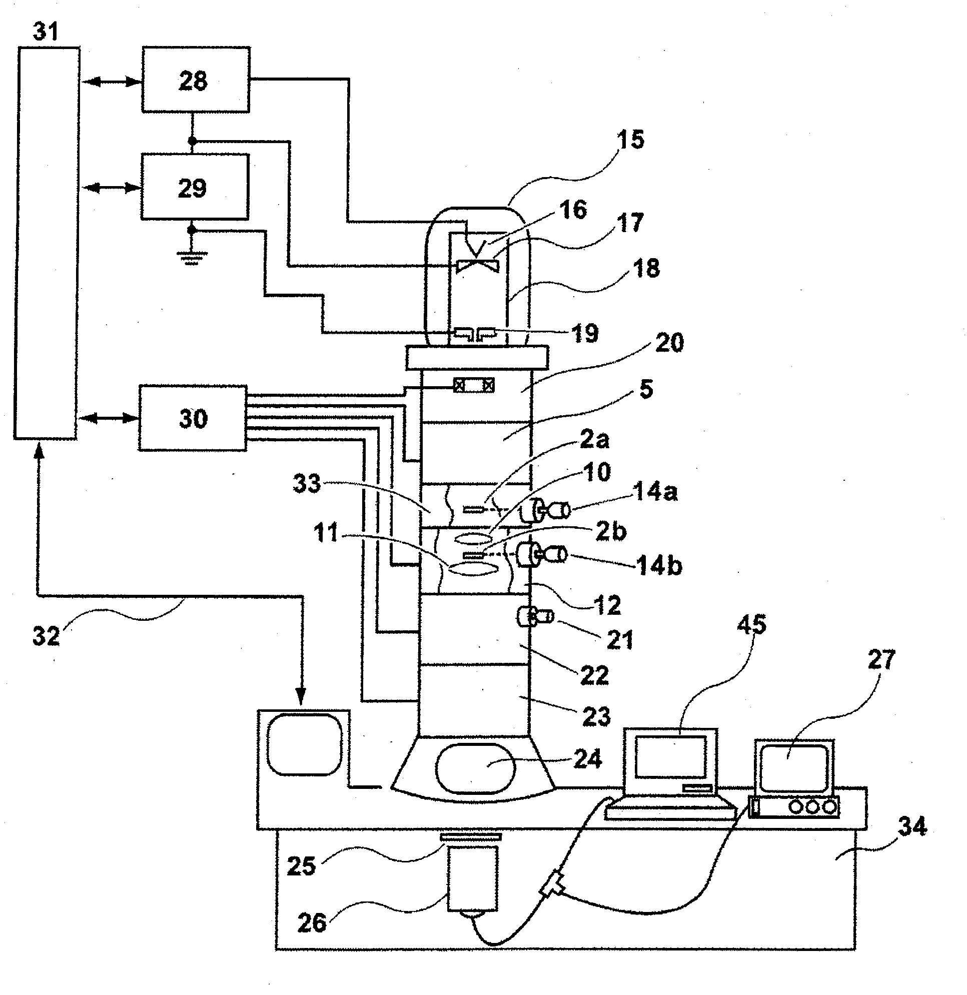
[0041]FIG. 4 schematically shows disposition of a TEM to which the present invention is applied. An electron gun 15 comprises an electron source 16 constituted of tungsten needle single crystal with a tip end sharpened, a lead-out electrode 17 placed at a position opposed thereto, a ground electrode 19 and an accelerating tube 18 for accelerating electrons which are led out. High voltage can be applied to the lead-out electrode 17 by a lead-out power supply 28 provided outside, and the lead-out electrode 17 can lead out electrons by application of voltage of about −3.0 to −2.5 kV between the electron source 16 and the lead-out electrode 17. Accelerating voltage for accelerating the electrons which are led out is supplied to the accelerating tube 18 by an accelerating voltage power supply 29. The electron beams emitted from the electron gun 15 are set at a desired irradiation condition in an intermediate chamber 20 including an alignment coil and a condenser lens 5, and are irradiate...

embodiment 2

[0057]FIG. 11 shows an example of application of the present invention to observation of a magnetic domain structure of a magnetic material. When only the specimen A 2a of the specimen position 7 outside the objective lens 12 is left on the optical axis and the influence of the lens magnetic field is small enough to be ignored, the magnetic specimen is placed at this position, and can be observed as if the specimen were disposed at the ordinary specimen position 8. FIG. 11 shows a Lorents microscope method for magnetic domain structure observation. The Lorents microscope method is the method for observing the boundary line (magnetic wall) of a magnetic domain as white and black contrast 48 on a surface formed by shifting the screen 13 by a defocus amount 47, since the magnetic information of the specimen cannot be obtained from the normal focus image 46 on the ordinary screen 13.

[0058]A similar observation method can be achieved by extremely decreasing an objective lens current. How...

embodiment 3

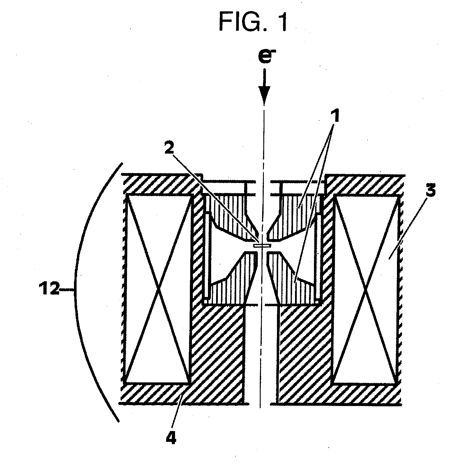
[0059]The present embodiment effectively uses the fact that the space around the specimen placed above the objective lens is not restricted by the objective lens magnetic pole piece. The outline is shown in FIG. 12. In the embodiment, a specimen holder 14a is disposed in a specimen chamber 33 directly above the objective lens12. Since a device and a mechanism which restrict the space do not exist in the specimen chamber 33, the space can be effectively used. FIG. 12 is an example in which a detector 37 of an X-ray is inserted into the space. The detector has been conventionally inserted in the vicinity of the magnetic pole pieces 1 of the objective lens and has been spatially restricted. Therefore, a capture angle for X-rays cannot be taken large, and there is the disadvantage of having to take a long integral time in order to perform highly accurate analysis from a very small X-ray amount. In the present embodiment, the capture angle can be made large, and the time required for ana...


PUM


Abstract

An electron beam observation device includes a mechanism which disposes a specimen at an upstream side in an electron beam traveling direction outside an objective lens, from which an image is transferred under a magnification of ⅕ to 1/30, in addition to an inside of the objective lens in which a specimen is disposed at a time of ordinary observation.

Description

BACKGROUND OF THE INVENTION[0001]The present invention relates to a device for observing an image of a specimen by using an electron beam and an image observation method using the same, and more specifically, the present invention uses a magnetic field at an upstream side in an electron beam traveling direction from the specimen to form the specimen image even in magnetic fields generated in an objective lens.[0002]Lenses used in electron beam devices include two types: one produces a lens effect by an electric field, and the other produces the similar effect by a magnetic field. In the case of electron microscopes available as commercial products at present, most of them are of the latter type, and are called electromagnetic lenses. Of the electromagnetic lenses which are incorporated in these electron beam devices, the objective lenses of a transmission electron microscope TEM and a scanning type electron microscope are important elements which determine the performance of the dev...

Claims


Application Information

Patent Timeline
IPC IPC(8): G01N23/04
CPCH01J37/141H01J37/20H01J37/26H01J2237/2802H01J2237/20H01J2237/201H01J2237/14
Inventor KASAI, HIROTOHARADA, KEN
Owner HITACHI LTD
Why Eureka
Try Eureka