Patterned magnetic recording medium and method for manufacturing same

a magnetic recording medium and patterned technology, applied in the field of magnetic recording mediums, can solve the problems of difficult to obtain all the desired characteristics from a protective layer, the protective layer in patterned magnetic recording media has not been studied, and the problem of not being able to achieve the desired characteristics, and achieve satisfactory sliding characteristics, adequate corrosion resistance of the magnetic layer, and high hardness

Inactive Publication Date: 2009-08-20
FUJI ELECTRIC DEVICE TECH CO
View PDF1 Cites 8 Cited by
  • Summary
  • Abstract
  • Description
  • Claims
  • Application Information

AI Technical Summary

Benefits of technology

[0017]As a result of assiduous studies to attain the above object, the inventor discovered that, by using an imprinting method, which is preferably a nano-imprinting method, a magnetic layer having a relief pattern corresponding to a desired relief pattern, which is preferably a nanometer-order relief pattern, demarcating information recording regions could easily be formed. Moreover, the inventor discovered that, by using t

Problems solved by technology

However, even when a single layer of ta-C is formed on a magnetic layer, it is extremely difficult to obtain all the desired characteristics sought from a protective layer.
Issues arising upon application of such proposals for the protective layer in patterned magnetic recording media have not been studied, however, because, in contrast with magnetic recording devices employing conventional CSS (contact start-stop) methods, magnetic recording devices adopting patterned magnetic recording media having a relief pattern and which are being studied as next-generation magnetic recording media, such as DTM and BPM, a method is employed in which the magnetic head performs information writi

Method used


Image

  • Patterned magnetic recording medium and method for manufacturing same
  • Patterned magnetic recording medium and method for manufacturing same
  • Patterned magnetic recording medium and method for manufacturing same

Examples


example 1

Sample 1

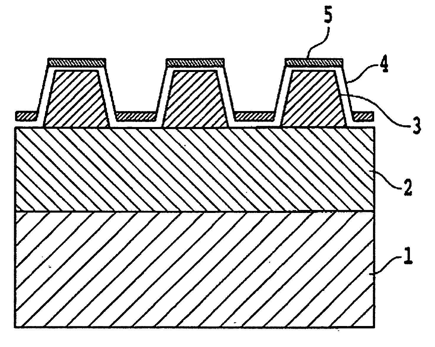
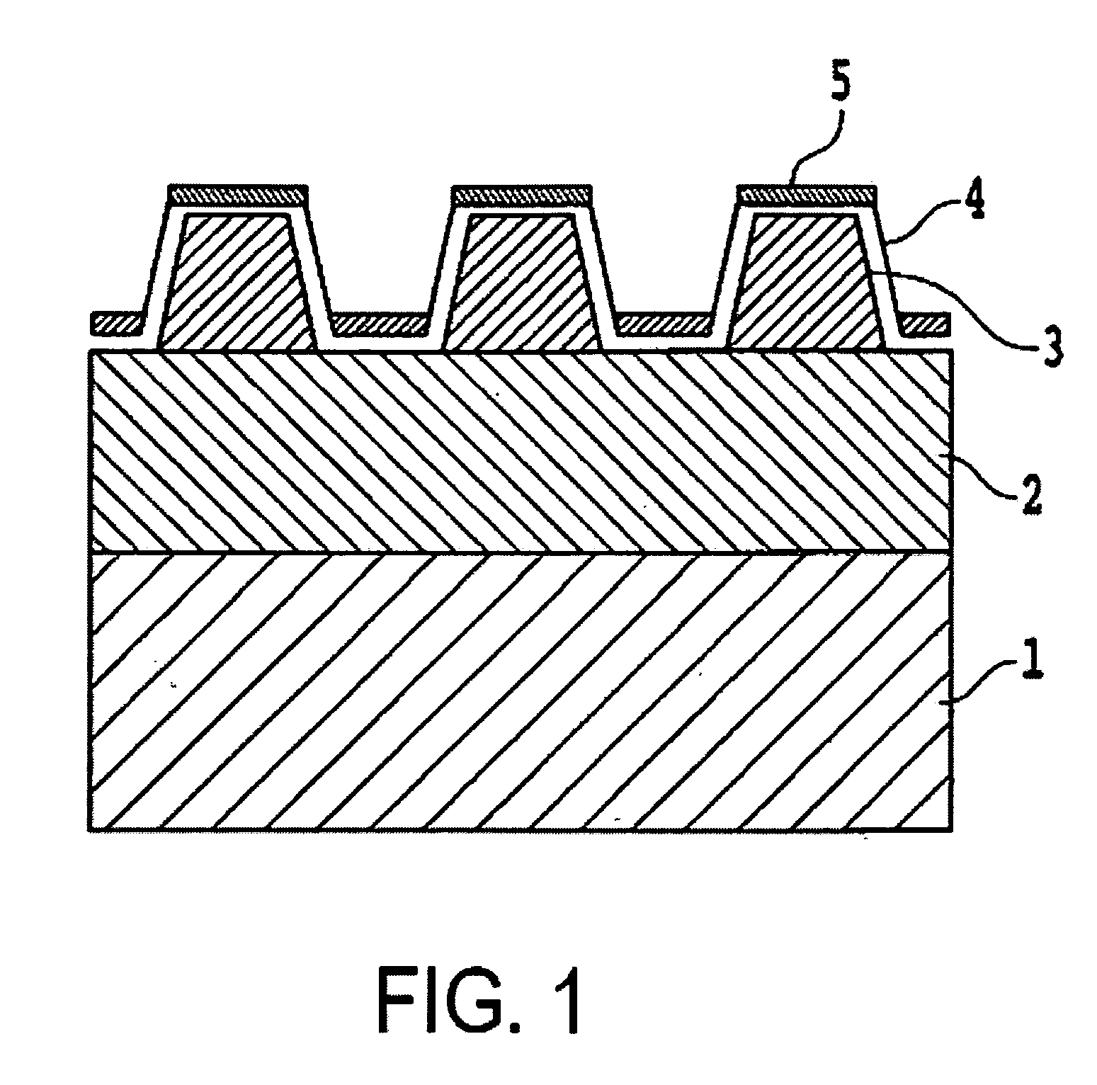
[0048]An underlayer 2 of film thickness 30 nm, comprising a material containing at least one among Cr, Ti and Co, was formed by a sputtering method on a glass substrate 1. On this underlayer 2 was formed, by a sputtering method, a magnetic layer 3 of thickness 10 nm, comprising Co—Cr—Pt alloy. On the magnetic layer 3 was further formed, by the plasma CVD method, a temporary protective layer 4a of film thickness 4 nm comprising carbon.

[0049]Onto the temporary protective layer 4a thus obtained, a spin coater was used to apply by spin coating a UV-hardening etching resist (product name PAK-01, manufactured by Toyo Gosei) to a thickness of 40 nm, and after eliminating solvent at 80° C., a quartz mold, on which was formed a track-shape relief pattern, was pressed with a pressure of 0.1 MPa onto the surface of the applied film. After hardening the etching resist by irradiation with ultraviolet rays through the quartz mold, the quartz mold was removed, and a track-shape pattern for...

example 2

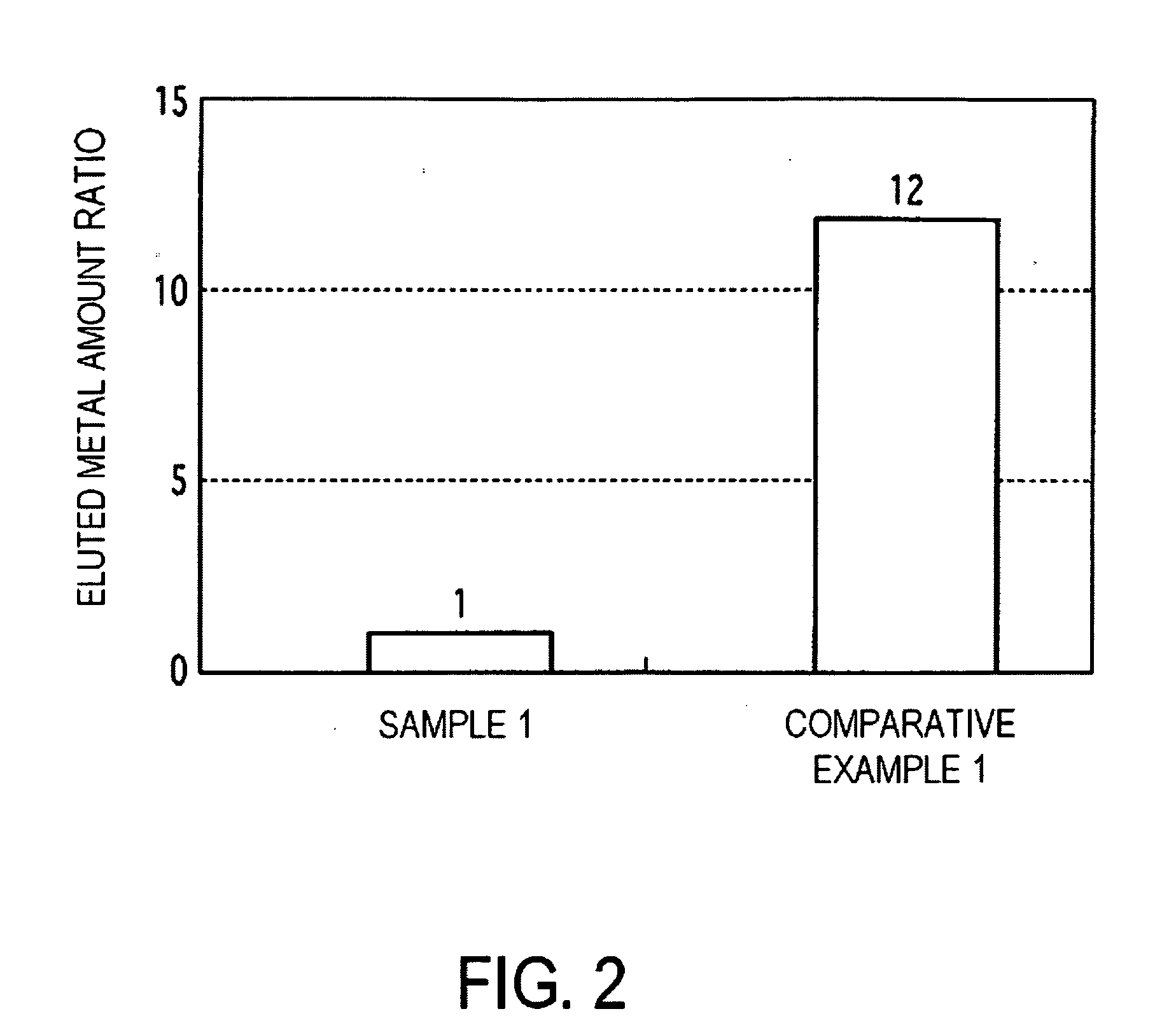
[0064]The same fabrication method as for Sample 1 in Example 1 was employed, except that the thickness of the magnetic layer 3 was 20 nm and the etch depth of the magnetic film 3 was 10 nm, to fabricate a patterned magnetic recording medium, in which the magnetic layer had a track-shape relief pattern with line widths of 60 nm, groove widths of 40 nm, and groove depths of 10 nm, the magnetic layer 3 existed in the convex pattern, in the layer below the convex pattern, and in the bottom portions of the concave pattern, and which had a first protective layer comprising DLC film and a second protective layer comprising ta-C film. The patterned magnetic recording medium thus obtained was subjected to sliding tests and then to metal elution tests, and results similar to those for Sample 1 of the above Example 1 were obtained.

example 3

[0065]After forming the underlayer 2 of thickness 70 nm comprising materials including at least one among Cr, Ti and Co, a UV-hardening etching resist was applied onto the underlayer 3, a quartz mold in which was formed a track-shape relief pattern was pressed against the etching resist applied film, the etching resist was hardened by irradiation with ultraviolet rays through the quartz mold, to form an etching pattern with pattern widths of 60 nm and pattern intervals of 40 nm, after which the underlayer 3 was etched along the etching pattern to form a relief pattern in the underlayer 3 having pattern widths of 60 nm, pattern intervals of 40 nm, and a pattern depth of 10 nm.

[0066]On the underlayer 3 with the relief pattern formed as described above, a magnetic layer 3 comprising a Co—Cr—Pt alloy was formed by evaporation deposition to a thickness of 10 nm, after which processes similar to those used in fabrication of Sample 1 in Example 1 were performed, forming on the magnetic lay...


PUM

PropertyMeasurementUnit
Widthaaaaaaaaaa
Widthaaaaaaaaaa
Widthaaaaaaaaaa

Abstract

A patterned magnetic recording medium includes a magnetic layer having a track-shape and/or dot-shape relief pattern which demarcates information recording regions; a first protective layer covering the magnetic layer; and a second protective layer formed on the first protective layer and including a tetrahedral carbon (ta-C) film. The first protective layer has excellent corrosion resistance and the second protective layer has excellent magnetic head sliding characteristics. A method for manufacturing the medium includes forming an etching pattern of photohardening etching resist on an underlayer or magnetic layer using an imprinting method and etching the underlayer or magnetic layer to form a relief pattern; forming the first protective layer on the relief pattern of the magnetic layer using plasma CVD; and forming the second protective layer including a tetrahedral carbon (ta-C) film, on at least respective top portions of the relief pattern, by a FCA method or by a FCVA method.

Description

CROSS-REFERENCE TO RELATED APPLICATION[0001]This Application claims the benefit of the priority of Applicant's earlier filed Japanese Patent Application No. 2008-037785, filed Feb. 19, 2008, the contents of which are incorporated herein by reference.BACKGROUND OF THE INVENTION[0002]1. Field of the Invention[0003]This invention relates to a magnetic recording medium, more specifically, to a patterned magnetic recording medium in which information recording regions are demarcated as a track-shape and / or dot-shape relief pattern, and to a method for manufacturing such a patterned magnetic recording medium.[0004]2. Background of the Related Art[0005]The recording capacity of magnetic recording media is rising rapidly, as a result of development of magnetic materials required for such media, adoption of perpendicular magnetization methods, narrowing of the gap between the magnetic head and the magnetic recording media surface through reduction of the magnetic head flying height during wr...

Claims


Application Information

Patent Timeline
IPC IPC(8): G11B5/72G11B5/66B05D3/06
CPCB82Y10/00G11B5/743G11B5/855G11B5/8408G11B5/82G11B5/72C23C14/06G11B5/74G11B5/84Y10S428/90
Inventor HORIGUCHI, MICHIKO
Owner FUJI ELECTRIC DEVICE TECH CO
Why Eureka
Try Eureka