Powder metal ultrasonic welding tool and method of manufacture thereof

a technology of ultrasonic welding and powder metal, which is applied in the direction of other manufacturing equipment/tools, non-electric welding apparatus,auxillary welding devices, etc., can solve the problems of local melting of plastic, metal melting, and metal heating, and achieve high friction, high wear composite materials, and adjust the strength and other physical characteristics.

Inactive Publication Date: 2009-08-27
FEDERAL MOGUL MOTORPARTS LLC
View PDF30 Cites 14 Cited by
  • Summary
  • Abstract
  • Description
  • Claims
  • Application Information

AI Technical Summary

Benefits of technology

[0013]The use of a powder metal material allows a great range of materials to be used in the tool. For example, the invention contemplates the use of metal alloys, blends and admixtures of metals, high wear composite materials, and high friction composite materials such as cermets. Further, powder metal material comprises an inherently porous structure so that additives can be used in the powder metal mix to adjust the strength and other physical characteristics. The powder metal material can also be treated to adjust the physical characteristics of the tool. The powder metal mixture, additives, and treatments can be selected to best suit the workpieces to be welded, so that the tool is compatible with more workpieces to be wel...

Problems solved by technology

In ultrasonic welding of thermoplastics, vibratory energy is applied to the plastic workpieces by an ultrasonic welding tool, causing local melting of the plastic.
The high frequency vibrations cause some heating of the metals, but not enough to melt the metals.
Ultrasonic soldering includes introducing the high frequency vibrations into molten solder and introducing a cavitation action at the welding tip, which disrupts and disperses the surface oxides.
Although ultrasonic welding has numero...

Method used


Image

  • Powder metal ultrasonic welding tool and method of manufacture thereof
  • Powder metal ultrasonic welding tool and method of manufacture thereof
  • Powder metal ultrasonic welding tool and method of manufacture thereof

Examples


Embodiment Construction

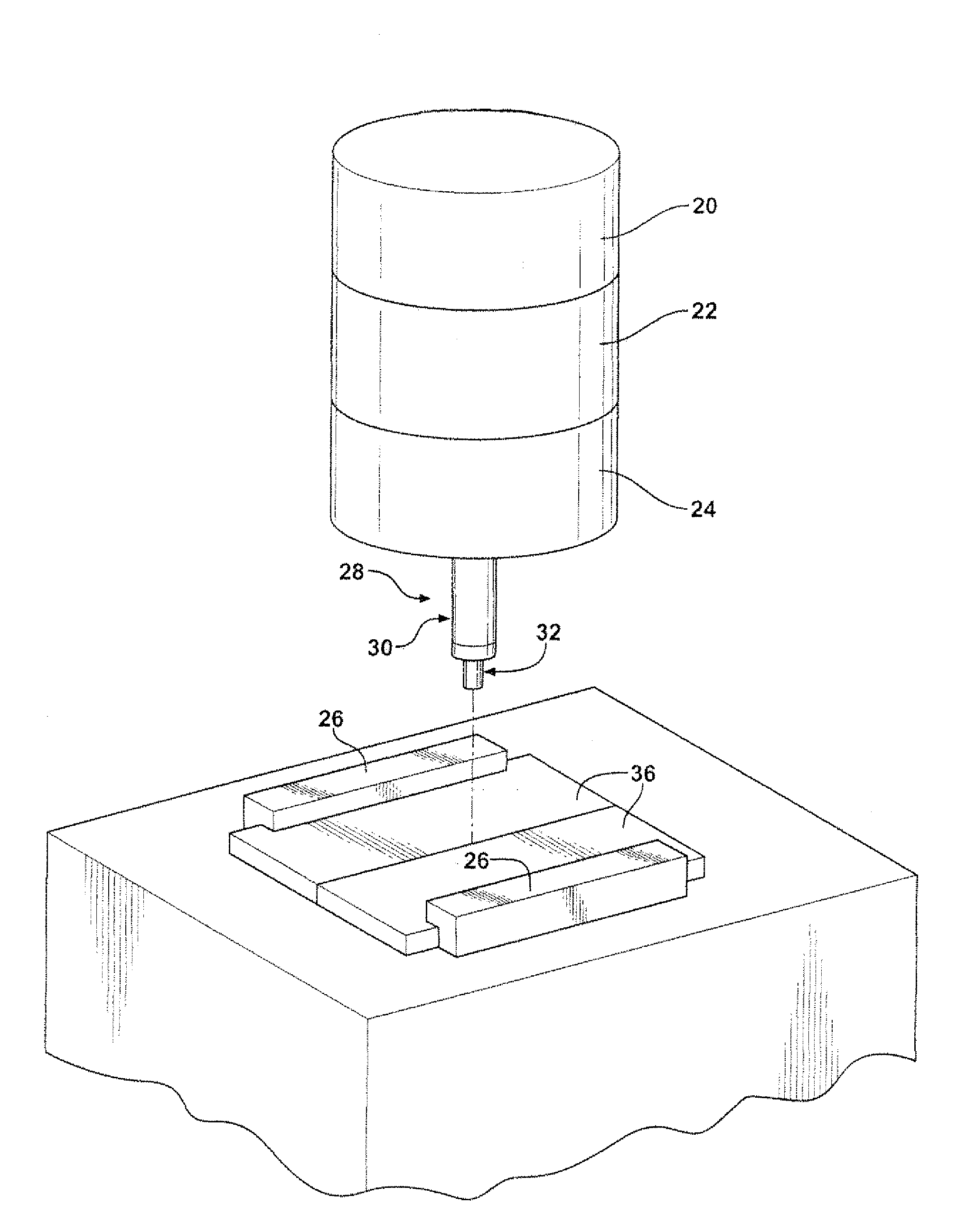
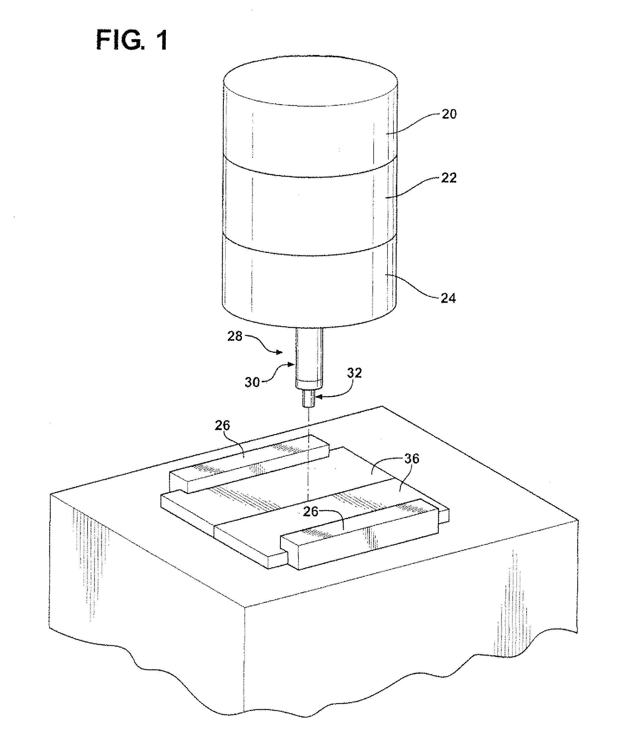
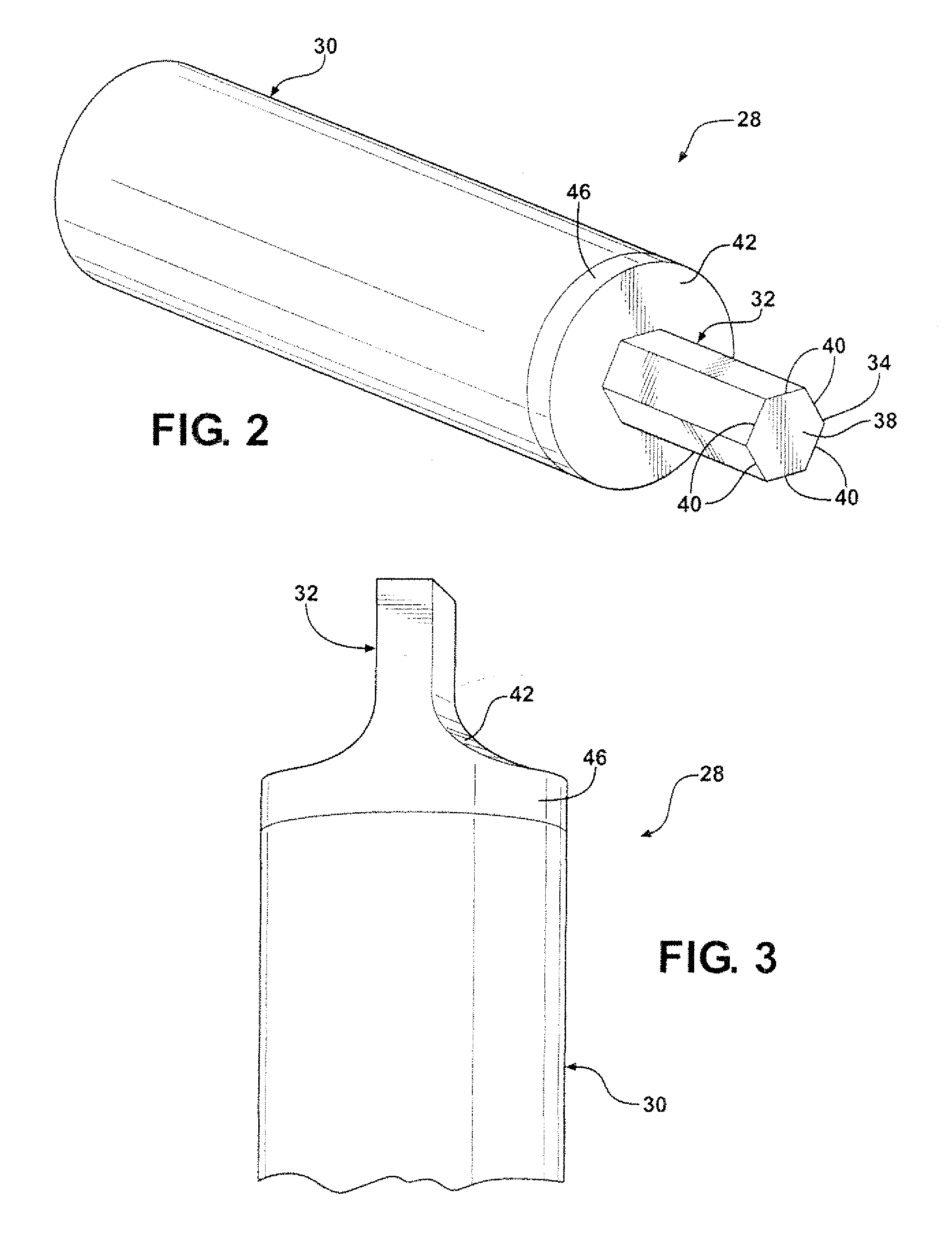
[0020]FIG. 1 illustrates a typically ultrasonic welding system including a power supply 20, converter 22, booster 24, press 26, and an ultrasonic welding tool 28 according to the invention. The ultrasonic welding tool is generally shown at 28 and comprises a body 30 and a welding tip 32 or probe extending axially from the body 30 to a working end 34 for applying a high frequency vibration to a workpiece 36 to be welded. The working end 34 includes a face 38 serving as the functional surface in contact with a workpiece 36 to effect the formation of an ultrasonic weld between two workpieces 36.

[0021]The ultrasonic welding tool 28 can take on any of a number of shapes and features. FIG. 2 illustrates one embodiment of the tool 28 wherein the body is generally cylindrical, and the welding tip 32 can be provided with flats 40. The present invention is not limited to any particular shape and / or size of the welding tip 32, nor are there limits to the number and shape of various surfaces of...


PUM

PropertyMeasurementUnit
Temperatureaaaaaaaaaa
Pressureaaaaaaaaaa
Wear resistanceaaaaaaaaaa

Abstract

An ultrasonic welding tool fabricated of powder metal material includes a body and a welding tip extending axially from the body to a working end. The powder metal material can be ferrous-based and admixed with additives, such as alumina, carbide, ferro-molybdenum, ferro-nickel, chrome or tribaloy. An exposed surface of the welding tip can comprise Fe3O4 oxides. The tool is compacted to the desired shape and sintered. The body can include a different second material compacted separately from the welding tip and then joined to the tip and sintered.

Description

CROSS REFERENCE TO RELATED APPLICATIONS[0001]This application is a Continuation in part of U.S. application Ser. No. 11 / 689,675, filed Mar. 22, 2007, which claim priority to U.S. Provisional Patent Application Ser. No. 60 / 802,753, filed May 23, 2006 and U.S. Utility patent application Ser. No. 11 / 689,186, filed Mar. 21, 2007.BACKGROUND OF THE INVENTION[0002]1. Technical Field[0003]This invention relates generally to ultrasonic welding tools, and more particularly to the materials and process used to make such tools.[0004]2. Related Art[0005]Ultrasonic welding is a technique used to join parts or workpieces comprising hard and soft plastics, and metals. In ultrasonic welding of thermoplastics, vibratory energy is applied to the plastic workpieces by an ultrasonic welding tool, causing local melting of the plastic. The vibrations are transferred through the plastic workpieces to the joint to be welded. The tool can remain in a single location on one of the workpieccs to be welded and ...

Claims


Application Information

Patent Timeline
IPC IPC(8): B23K20/10B22F3/12B22F1/00B22F7/02
CPCB22F3/26Y10T428/12028B23K20/106B23K20/1255B29C65/0681B29C65/08B29C66/1142B29C66/43B29C66/80B29K2101/12B29K2105/251B29K2705/00C22C1/1078B22F7/062B22F7/06B22F2302/253B22F2302/256B29C66/81429B22F2302/25B22F2302/205B22F2005/002B22F2003/242B22F2302/45B22F5/00B22F3/12B29C65/00B29K2995/007B29C66/81264B29C66/81241
Inventor CHRISTOPHERSON, JR., DENIS
Owner FEDERAL MOGUL MOTORPARTS LLC
Why Eureka
Try Eureka