Surface treatment method and repair method

a surface treatment and repair method technology, applied in the direction of solid-state diffusion coating, wind motor with perpendicular air flow, wind motor with parallel air flow, etc., can solve the problems of difficult application of these methods, limited surface area, and site requirements for such performan

Inactive Publication Date: 2009-08-27
IHI CORP
View PDF50 Cites 10 Cited by
  • Summary
  • Abstract
  • Description
  • Claims
  • Application Information

AI Technical Summary

Problems solved by technology

Sites required to have such performance are limited in these components and also limited in surfaces thereof.
As methods applicable thereto, PVD, CVD and thermal spraying can be exemplified, however, these methods may raise some technical problems in which some selected materials make it difficult to apply these methods, require very long time for processing, and require additional process steps such as masking of peripheries of subject sites so as to localize the coatings in the sites.
H8-300227, A problem of this art is to often form a porous coating on any occasions depending on kinds of ceramics and / or operation conditions.
As a porous coating is poor in bonding force among particles, it may be hard to ensure sufficient strength for the coating.

Method used


Image

  • Surface treatment method and repair method
  • Surface treatment method and repair method
  • Surface treatment method and repair method

Examples


first embodiment

[0020]the present invention will be described hereinafter with reference to FIG. 1 through FIG. 4.

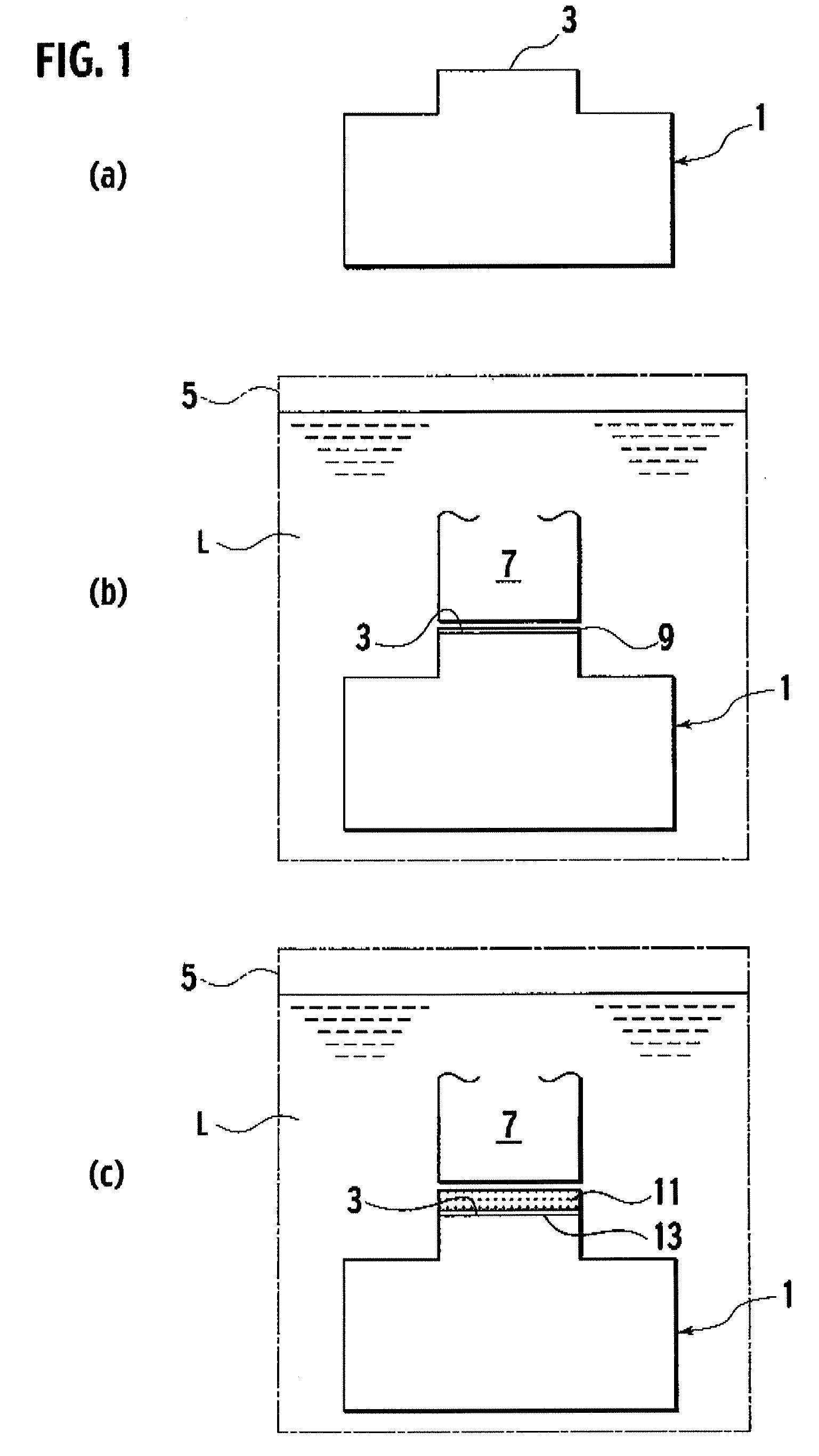
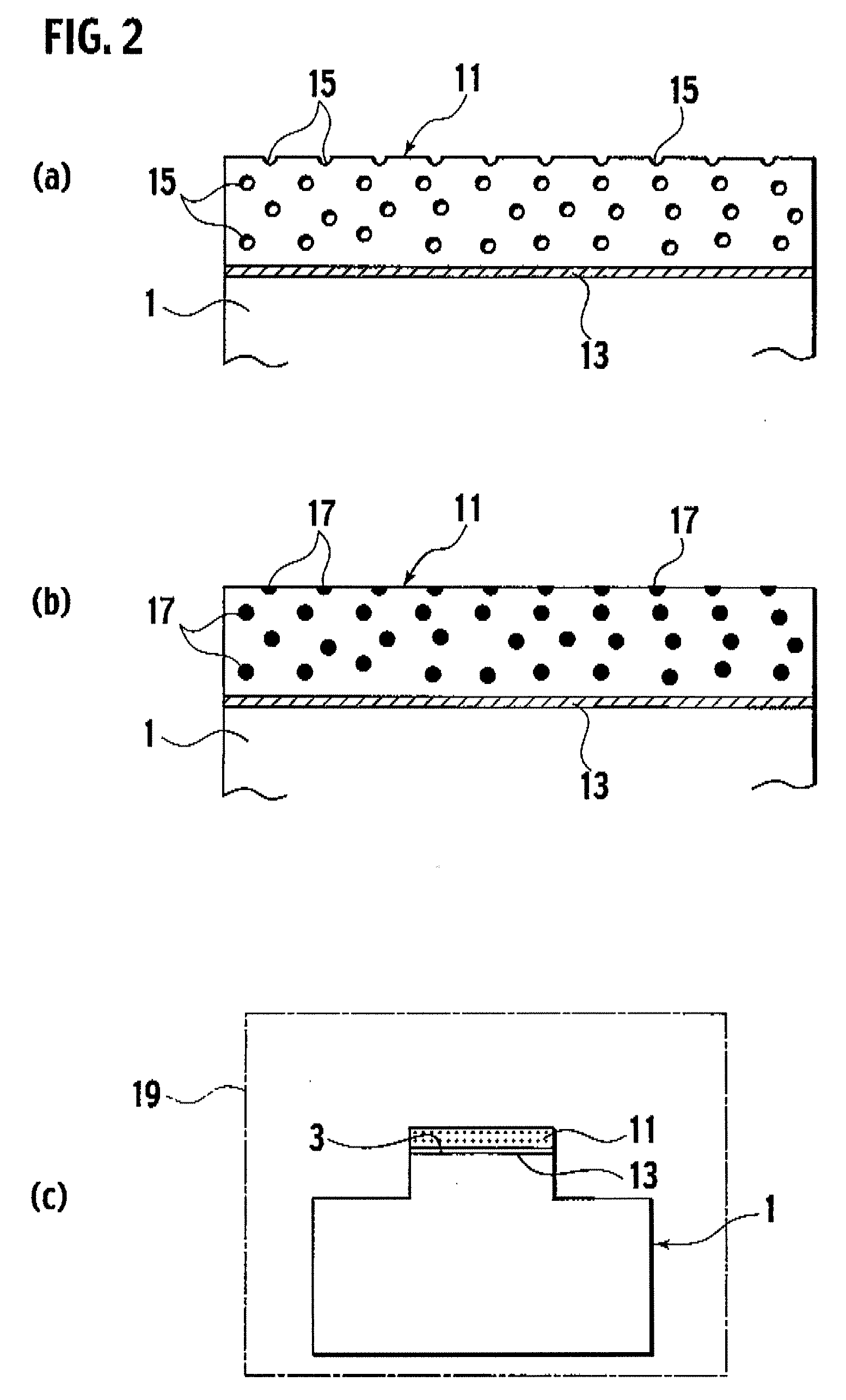
[0021]A surface treatment method in accordance with the first embodiment of the present invention is a method for treating a subject portion 3 of a subject body 1 as shown in FIG. 1(a) with a surface treatment and includes the following steps of a (I) thin-film formation step, a (II) buildup layer formation step, a (III) lubricant fillingstep, and a (IV) high-temperature keeping step.

(I) Thin-Film Formation Step

[0022]As shown in FIG. 1(b), the subject body 1, as a workpiece of the electric spark machine, is made closed to a working electrode 7 in a processing bath 5 of the electric spark machine. Then pulsing discharge is generated between the subject portion 3 of the subject body 1 and the working electrode 7 in an oil L stored in the processing bath 5. Thereby, a deposition by discharge deposition is formed as a thin film 9 on the subject portion 3 of the subject body 1.

[0023]Here, th...

second embodiment

[0039]the present invention will be described hereinafter with reference to FIG. 5 through FIG. 9.

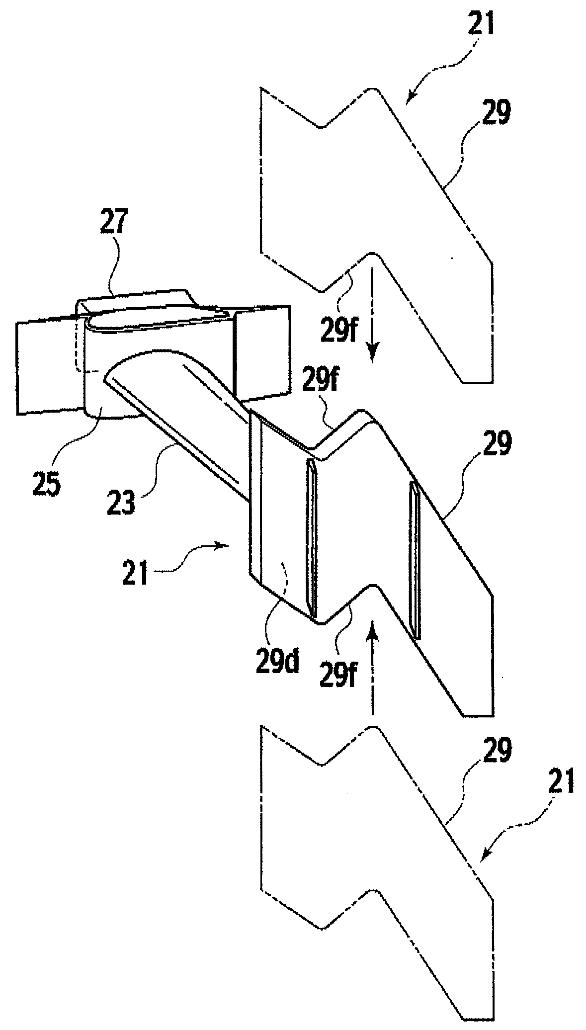
[0040]As shown in FIG. 5, a turbine rotor blade 21 as a subject to repair by a repair method in accordance with the second embodiment is one of engine components used in a gas turbine engine such as a jet engine, and is provided with a blade 23, a platform 25 formed in a unitary body with a proximal end of the blade 23 and provided with inner flow paths, a dovetail 27 formed in a unitary body with the platform 25 and configured to fit with a dovetail groove (not shown) of a turbine disk, and a shroud 29 formed in a unitary body with a distal end of the blade 23 and provided with an outer flow path 29d.

[0041]Here, as shown in FIG. 6 (a), as a pair of abrasion surfaces 29f of the shroud 29 of the turbine rotor blade 21 easily have defects such as wear caused by abrasion with an abrasion surface 29f of a shroud 29 of an adjacent turbine rotor blade 21, the abrasion surface 29f of the shro...


PUM

PropertyMeasurementUnit
thicknessaaaaaaaaaa
thicknessaaaaaaaaaa
peak currentaaaaaaaaaa

Abstract

A method for forming a dense coating on a limited region of a subject body is disclosed. The method is composed of the steps of: applying one selected from the group of a compressed body of a powder of a metal and a sintered compressed body of a powder of a metal to a working electrode; executing discharge deposition to deposit a first coating from the working electrode on the subject body by applying the subject body as a workpiece of the discharge deposition; executing discharge deposition to deposit a second coating from the working electrode on the first coating by applying the subject body as a workpiece of the discharge deposition; and heating the subject body in one selected from the group of a vacuum, an air and an oxidizing atmosphere so as to densify the second coating or oxidizing the second coating at least in part to generate a solid lubricant substance.

Description

TECHNICAL FIELD[0001]The present invention relates to a method using electric discharge for forming a coating or a buildup on a desired site of a workpiece such as a component of a gas turbine engine and a repair method therewith.BACKGROUND ART[0002]As a gas turbine engine carries out high-speed revolution under high temperatures, its components are required to have excellent performance in abrasion resistance, heat resistance and / or high-temperature corrosion resistance. Sites required to have such performance are limited in these components and also limited in surfaces thereof. Therefore, it is often executed to have proper materials such as ceramics formed as coatings on base members. As methods applicable thereto, PVD, CVD and thermal spraying can be exemplified, however, these methods may raise some technical problems in which some selected materials make it difficult to apply these methods, require very long time for processing, and require additional process steps such as mas...

Claims


Application Information

Patent Timeline
Patent Type & Authority Applications(United States)
IPC IPC(8): F01D5/14B23P6/00B05D5/08
CPCC23C8/02C23C26/00F01D5/288Y10T29/49318F05D2230/40Y10T29/49728F05D2230/30
Inventor OCHIAI, HIROYUKIWATANABE, MITSUTOSHIFURUKAWA, TAKASHIOTERA, ISSEI
Owner IHI CORP
Why Eureka
Try Eureka