
Plasma processing apparatus and impedance adjustment method

a technology of impedance adjustment and processing apparatus, which is applied in the direction of instruments, fluid pressure measurement, gas-filled discharge tubes, etc., can solve the problems of a minor difference in the impedance between the apparatus or cleaning cycle, and achieve the effect of improving the uniformity of the plasma spatial distribution, reducing the impedance difference, and high impedance adjustment accuracy

Active Publication Date: 2009-09-10
TOKYO ELECTRON LTD
View PDF5 Cites 9 Cited by
  • Summary
  • Abstract
  • Description
  • Claims
  • Application Information

AI Technical Summary

Benefits of technology

[0008]It is, therefore, a primary object of the present invention to provide a plasma processing apparatus capable of adjusting an impedance on the side of a plasma source and solving an impedance difference between apparatuses or cleaning cycles.
[0016]In accordance with the present invention, there are provided a resonance circuit, a variable impedance unit installed on a power feed line of a first electrode and a detector for detecting an apparatus state to search a resonance point of the resonance circuit. In a state where plasma is generated, a signal of the apparatus state of the detector is detected while varying a value of the variable impedance unit, thereby searching a resonance point of the resonance circuit. Also, by adjusting an impedance on the side of the plasma source while setting a value of the variable impedance unit at the resonance point to a reference value, it is possible to minimize an impedance difference on the side of the plasma source between apparatuses or cleaning cycles due to dimensional tolerances or attachment errors of parts. Furthermore, since the adjustment can be performed in a state where the plasma is generated, a high impedance adjusting accuracy can be achieved. Moreover, since neither special measuring device nor a test device is used, it is advantageous in terms of cost. In addition, most of the adjustment can be automatically carried out and thus, there is no artificial mistake that can be made.
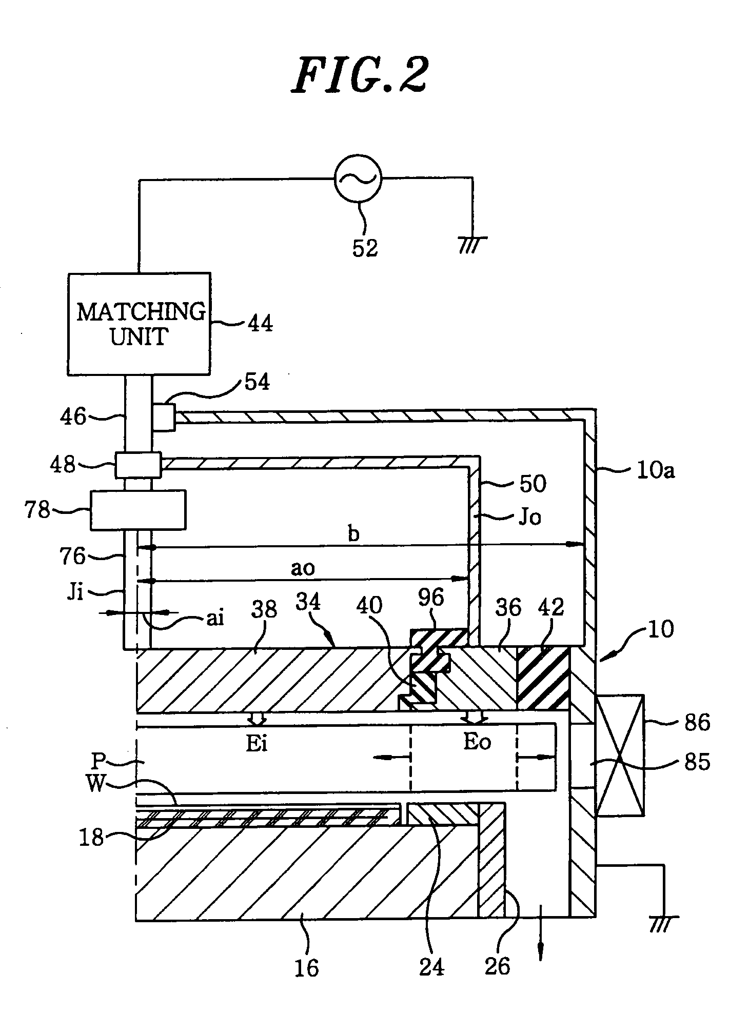
[0017]In the plasma processing apparatus of the present invention, the first electrode is divided into an inner electrode and an outer electrode, and a variable impedance unit is installed on a power feed line of the inner electrode or that of the outer electrode. In such plasma processing apparatus, a uniformity of a plasma spatial distribution can be improved by controlling an electric field of an inner and that of an outer portion on a plasma contact surface of the first electrode. Also, the impedance adjustment can be performed by using the variable impedance unit and the resonance circuit in which a radio frequency current flows in the inner electrode. Especially, by installing the variable capacitor on the power feed line of the inner electrode, the impedance adjustment can be carried out more effectively.

Problems solved by technology

In such a plasma processing apparatus, there is given rise on the side of a plasma source to a minor difference in the impedance between apparatuses or cleaning cycles due to dimensional tolerances or attachment errors of parts.
However, the conventional plasma processing apparatus is not provided with a mechanism for solving the mechanical difference in impedance, so that process characteristics become different from one apparatus to another or from one cleaning cycle to another.

Method used


Image

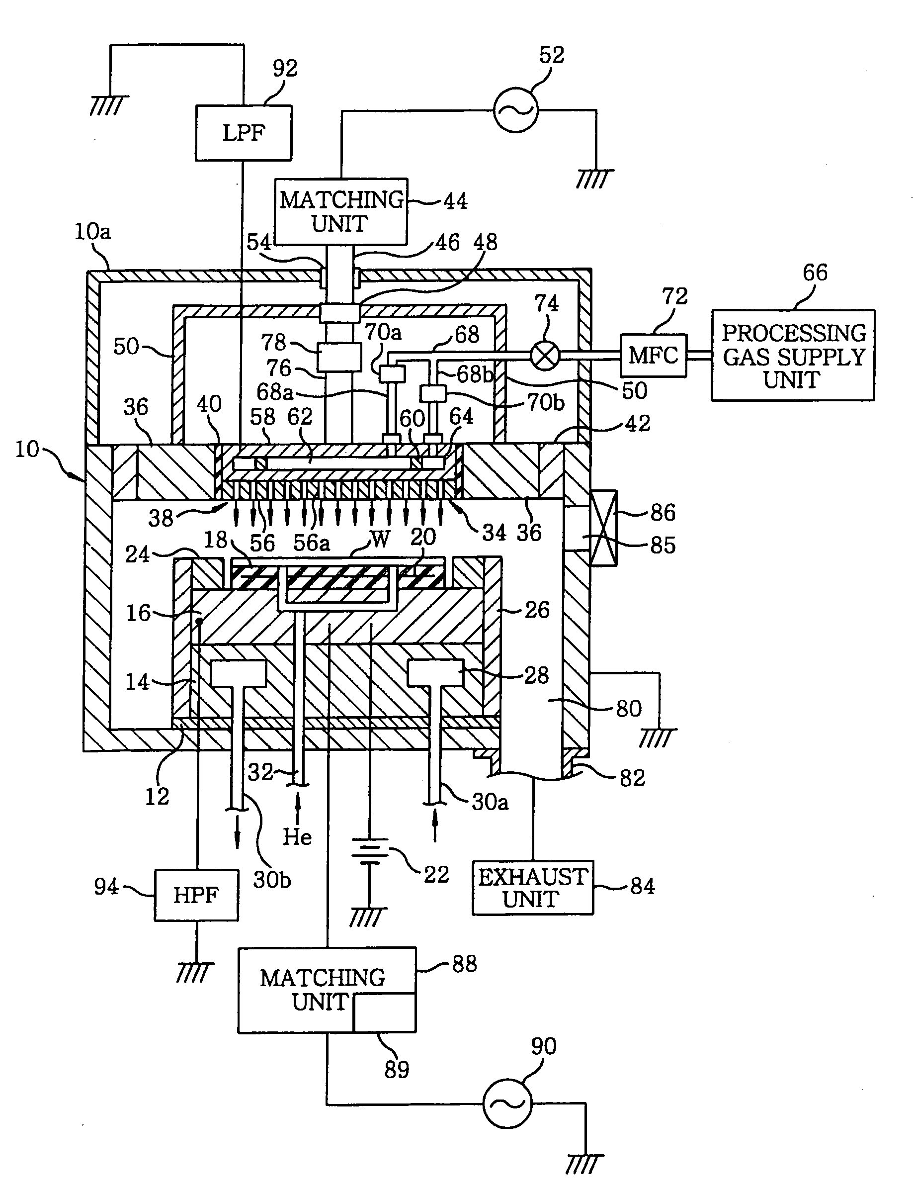
  • Plasma processing apparatus and impedance adjustment method
  • Plasma processing apparatus and impedance adjustment method
  • Plasma processing apparatus and impedance adjustment method

Examples


Embodiment Construction

[0031]Hereinafter, preferred embodiments of the present invention will be described in detail with reference to the accompanying drawings.

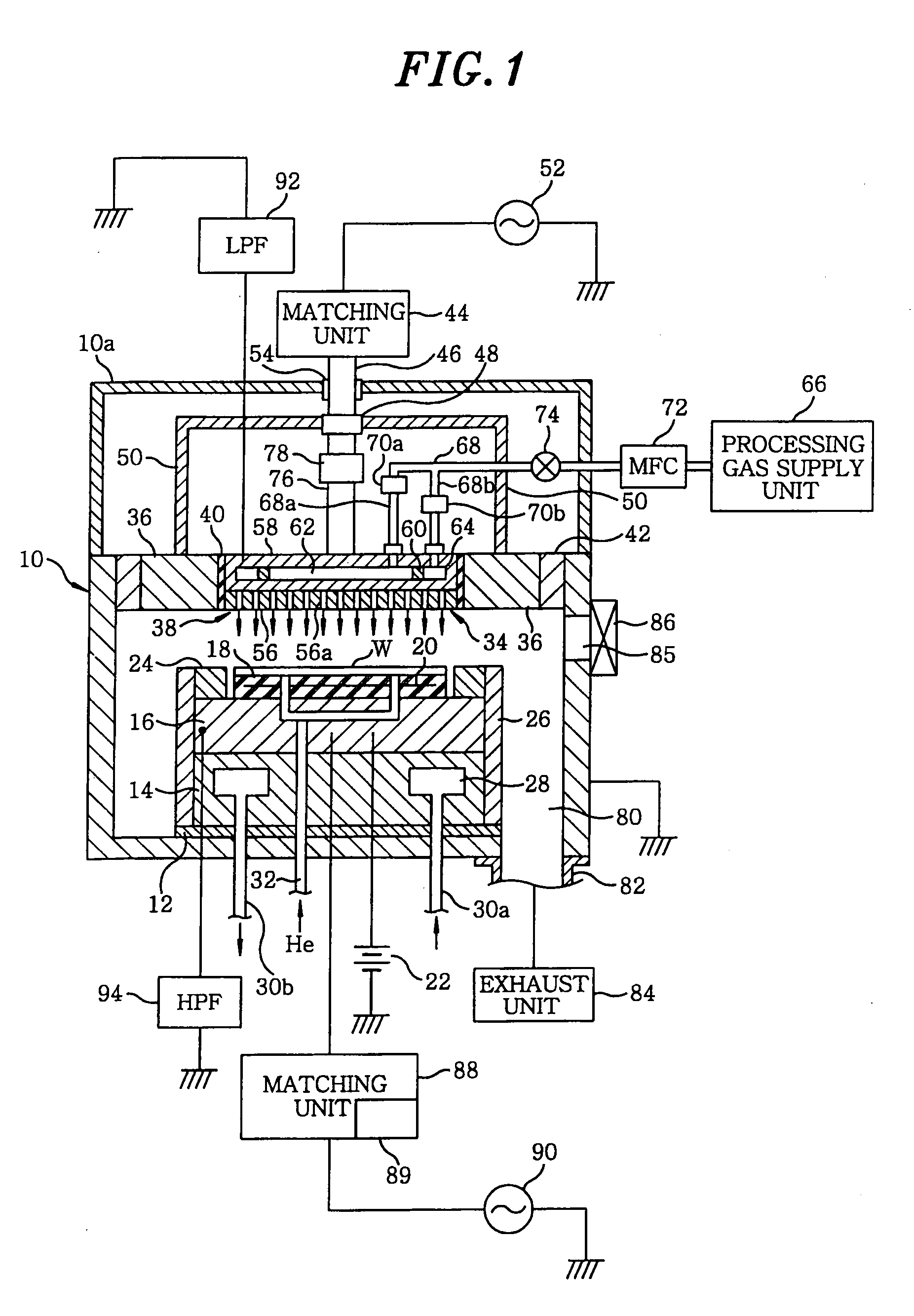
[0032]FIG. 1 is a schematic cross sectional view of a plasma etching apparatus in accordance with a preferred embodiment of the present invention.

[0033]The plasma etching apparatus is a capacitively coupled parallel flat type plasma etching apparatus having an approximately cylindrical chamber (processing vessel) 10 made of aluminum whose surface is treated by an anodic oxidization. The chamber 10 is frame grounded.

[0034]A columnar susceptor support 14 is provided on a bottom of the chamber 10 via an insulating plate 12 made of ceramic or the like. Further, a susceptor 16 made of, e.g., aluminum is installed on the susceptor support 14. The susceptor 16 forms a lower electrode, and a semiconductor wafer W as a substrate to be processed is mounted thereon.

[0035]Provided on top of the susceptor 16 is an electrostatic chuck 18 for adsorptively holdin...


PUM

PropertyMeasurementUnit
radio frequencyaaaaaaaaaa

Abstract

A plasma processing apparatus, for performing a plasma processing on a substrate to be processed by generating a plasma of the processing gas in an evacuable processing chamber, includes an impedance adjusting mechanism. The impedance adjusting mechanism is provided with a resonance circuit formed to allow a radio frequency current to flow into the first electrode; a variable impedance unit installed on a power feed line to the first electrode; a detector for detecting an apparatus state to be used to search a resonance point of the resonance circuit; and a controller for searching a resonance point of the resonance circuit by detecting a signal of the apparatus state of the detector while varying a value of the variable impedance unit in a state where the plasma is formed and then adjusting the value of the variable impedance unit at the resonance point to a reference value.

Description

CROSS-REFERENCE TO RELATED APPLICATIONS[0001]The present application is a divisional application of and claims priority to U.S. application Ser. No. 11 / 142,391, filed Jun. 2, 2005, of which the entire content is hereby incorporated by reference, with the present application also claiming priority to predecessors of the '391 application as follows. U.S. application Ser. No. 11 / 142,391 claims priority to Japanese Application No. 2004-165074, filed Jun. 2, 2004 and U.S. Provisional Application No. 60 / 589,809, filed Jul. 22, 2004.FIELD OF THE INVENTION[0002]The present invention relates to a plasma processing apparatus for performing a plasma processing on a substrate such as a semiconductor substrate or the like and an impedance adjustment method employed in a plasma processing apparatus.BACKGROUND OF THE INVENTION[0003]For example, in a semiconductor device manufacturing process, a plasma processing such as an etching, a sputtering, a chemical vapor deposition (CVD) or the like is per...

Claims


Application Information

Patent Timeline
Patent Type & Authority Applications(United States)
IPC IPC(8): G01R31/00B44C1/22
CPCH01J37/32174H01J37/32082
Inventor HIRANO, TAICHI
Owner TOKYO ELECTRON LTD
Learn More