Control of bubble formation in extracorporeal circulation

a technology of extracorporeal circulation and control of bubbles, applied in water/sludge/sewage treatment, dialysis, solvent extraction, etc., can solve problems such as annihilating bubbles completely

Inactive Publication Date: 2009-09-17
SIFR2000
View PDF14 Cites 15 Cited by
  • Summary
  • Abstract
  • Description
  • Claims
  • Application Information

AI Technical Summary

Benefits of technology

[0015]The subatmospheric pressure in the above described airtight gas exchange means will not only extract dissolved gas of the blood but also induce formed bubbles entering into the gas exchange means to increase in volume proportionally. Since there is formation of a denatured layer of lipoproteins in the gas-liquid interface of blood, the transient volume increase of a bubble passing through a gas exchange means with subatmospheric pressure may enlarge the total bubble surface area and thus the total amount of irreversibly denatured lipoprotein. This can be counteracted by the application of a proportionally increased hydrostatic blood pressure in the blood compartment of the gas exchange means.
[0016]Furthermore, by increasing the hydrostatic pressure of a liquid containing bubbles it is possible to force gas molecules from the gas bubble into a soluble state in the liquid. Hydrostatic pressure high enough may even annihilate the bubble completely. In one embodiment of the invention, a supplementary device for the temporary increase of hydrostatic pressure is incorporated for this purpose in the tubing of the extracorporeal circuit, preferably between the flow control means and the gas exchange means.

Problems solved by technology

Hydrostatic pressure high enough may even annihilate the bubble completely.

Method used


Image

  • Control of bubble formation in extracorporeal circulation
  • Control of bubble formation in extracorporeal circulation
  • Control of bubble formation in extracorporeal circulation

Examples


first embodiment

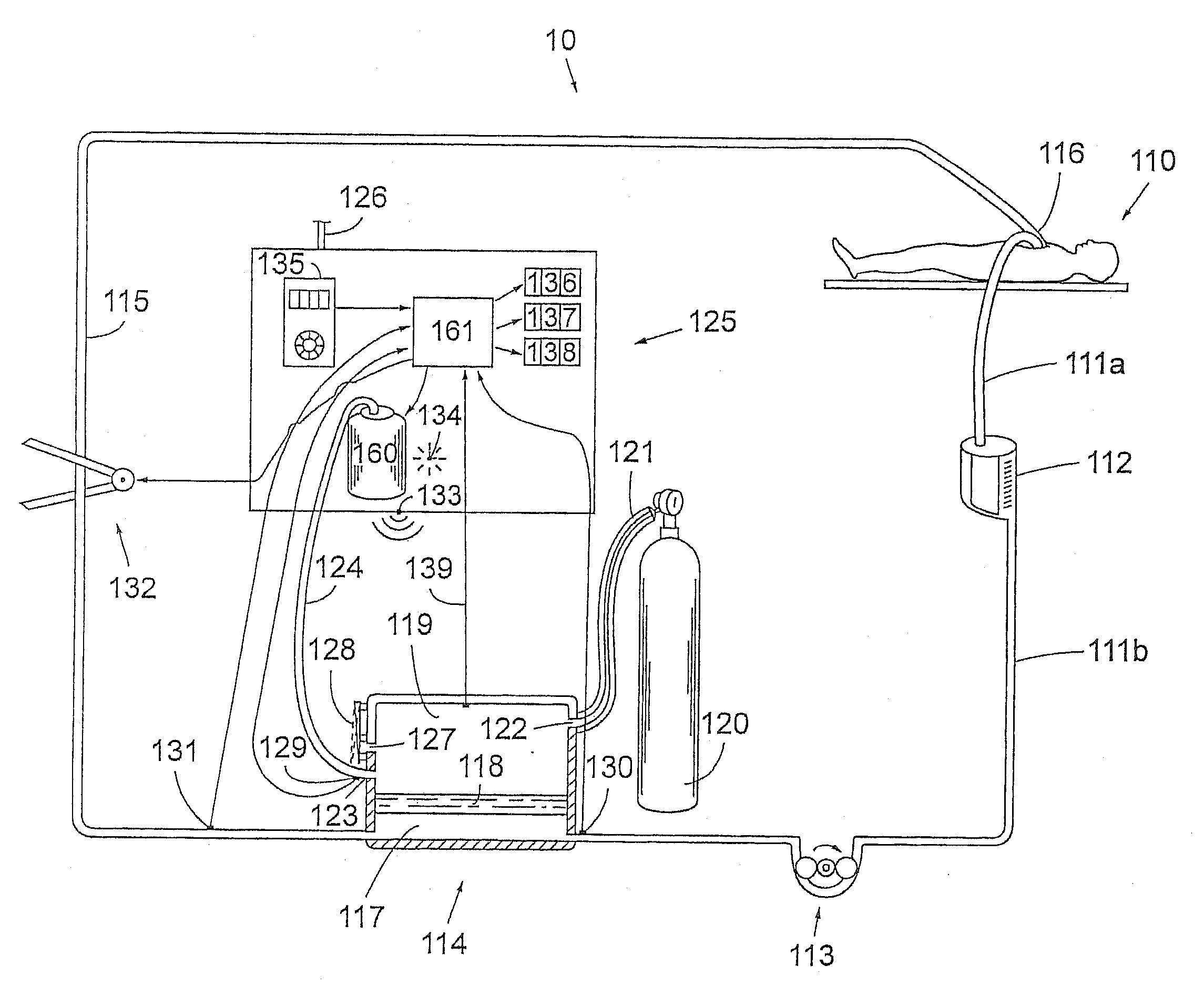
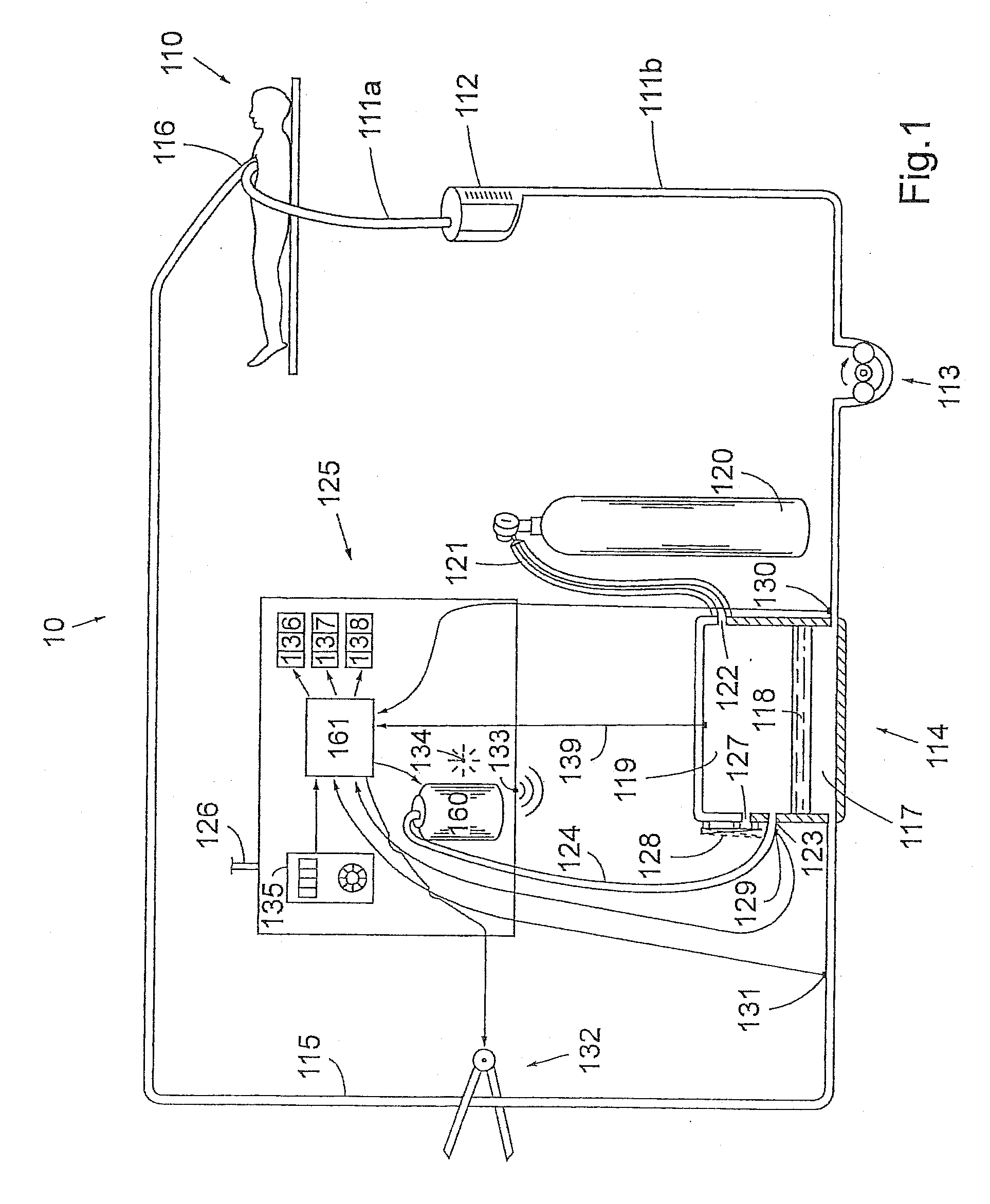
[0023]FIG. 1 schematically depicts a system according to the present invention, which system 10 can be used in e.g. open heart surgery. The figure shows how the application of vacuum to a gas exchange means, such as an oxygenator, can be employed and also how an increased hydrostatic blood pressure during blood passage through the oxygenator can be generated according to the invention and setup of the device during extracorporeal perfusion.

[0024]An embodiment of the inventive system 10, according to FIG. 1, comprises tubings 111a by means of which venous blood can be diverted from a patient 110 to an extracorporeal venous reservoir 112. In this description, the tubing 111a will also be referred to as a venous line 111a. However it should be understood that the tubing also can be an arterial line in applications where arterial blood is to be withdrawn from the patient. The venous reservoir 112 is configured to collect, by gravity force or by an applied subatmospheric pressure, the ve...

second embodiment

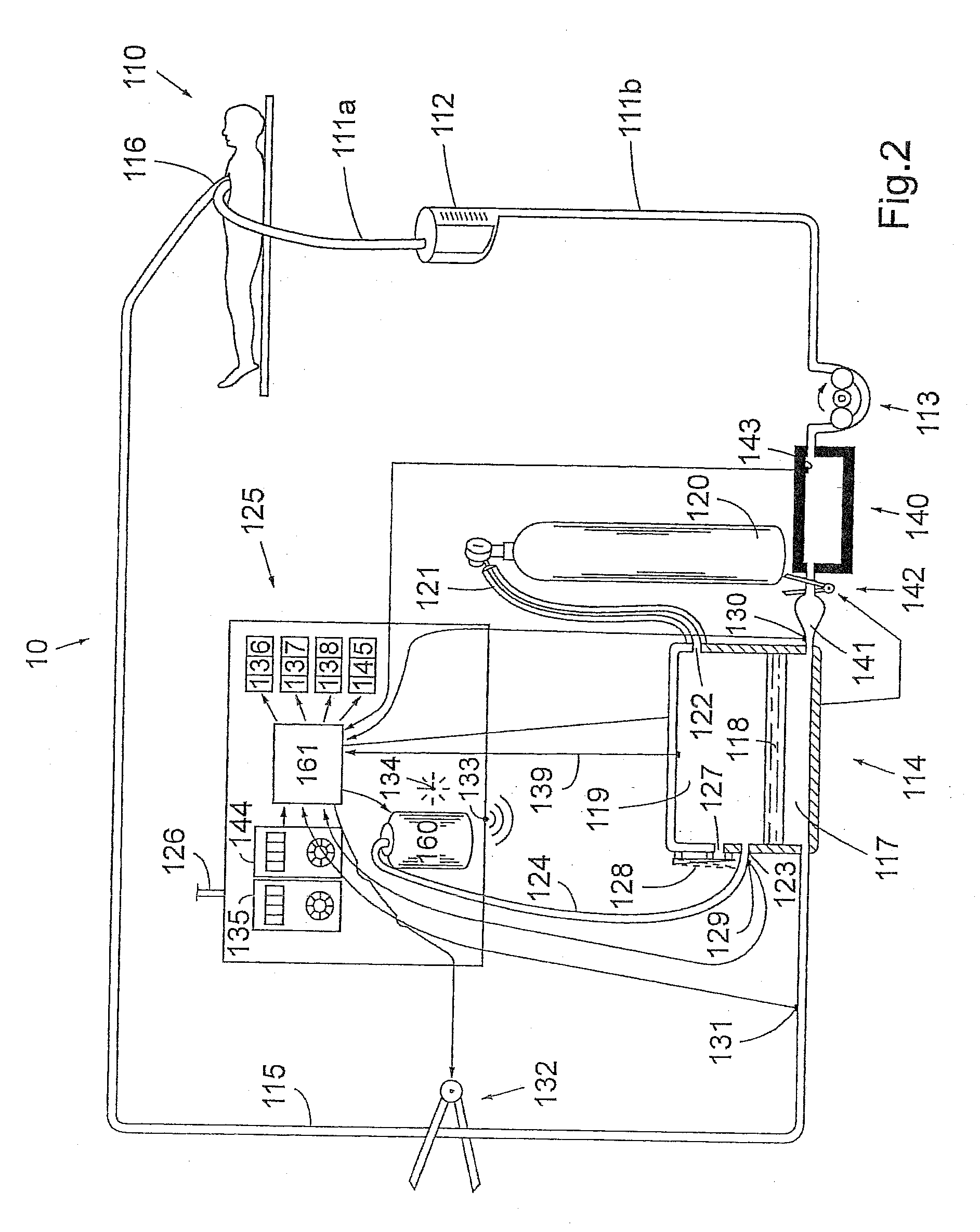
[0039]the invention comprises means for the temporary increase of hydrostatic pressure of the blood in the extracorporeal circuit. The purpose of this pressure increasing means is to reduce bubble volume of gas by application of an increased hydrostatic pressure to the bubble-carrying liquid / blood. The increased hydrostatic pressure of blood will be propagated into the gas bubble, thus forcing gas from the bubble into solution, i.e. from gas phase to liquid phase. Subsequently, a new steady state is reached rendering the bubbles smaller not only because of the higher hydrostatic pressure but also from the loss of a portion of the original contained gas of the bubbles that becomes dissolved in the blood. At high enough levels of hydrostatic pressure applied and long enough time period of its application, even a complete annihilation of bubbles may be achieved.

[0040]FIG. 2 shows schematically the second embodiment of the invention comprising means for the temporary increase of hydrost...

third embodiment

[0046]It is important to be able to measure changes in bubble formation when the methods and equipment according to this invention are employed. In the invention, the inventive system contains means to monitor and document the occurrence of bubbles more properly than currently employed. Heart-lung machines contain bubble monitoring devices with sensors to be attached to the tubing and which are configured to warn the perfusionist when bubbles appear and they may also be configured to automa-tically halt the main pump in case larger bubbles occur. The sensitivity of the bubble sensors of heart-lung machines in common use, e.g. in Jostra HLM 20 and Stockert S3, is 300 micrometers, which is to be compared with the size of blood capillaries which may be in the range of the diameter of a single red blood cell i.e. 7 micrometers. The bubble detecting device already equipped into a heart-lung machine may therefore be too insensitive.

[0047]FIG. 3 shows schematically a third embodiment of th...


PUM


Abstract

The invention relates to control of bubble formation in a fluid during extracorporeal circulation. A fluid supply means (111a) is configured to supply fluid to the extracorporeal circuit (111a, 111b, 113, 114, 115, 116), a flow control means (113) is connectable to the extracorporeal circuit and configured to control the flow of the fluid in the circuit; a gas exchange means (114) is connectable to the circuit and configured to gas exchange of the circulated fluid; an antibubble control unit (125) is connectable to an outlet (123) of the gas exchange means and configured to control the total gas pressure over a gas-exchange membrane (118) of the gas exchange means, whereby the amount of gas in the fluid leaving the gas exchange means can be controlled; and fluid return means (115, 116) is connected to the gas exchange means and configured to reintroduce the fluid into the patient.

Description

TECHNICAL FIELD[0001]The present invention relates to control of bubble formation in a body fluid during extracorporeal circulation. More precisely, the present invention relates to minimization of the bubble formation.BACKGROUND OF THE INVENTION[0002]Primarily during heart operations there is a transient need to replace the function of the heart and lungs by artificial means. Also in more chronic disease states as e.g. during severe pulmonary, cardiac, or renal failure, maintenance of life can be upheld by different artificial means until an organ for transplantation becomes available. In many clinical situations there is a need for an extracorporeal circuit wherein the artificial organ is incorporated.[0003]The contact of blood on surfaces made out of foreign material inevitably initiates blood coagulation and the formation of clots. This is controlled by the use of anticoagulant drugs. Also gas bubbles are easily formed in blood, which is propelled into the circulation of a livin...

Claims


Application Information

Patent Timeline
Patent Type & Authority Applications(United States)
IPC IPC(8): A61M1/34B01D61/32
CPCA61M1/1698A61M1/3627A61M1/3626A61M1/32A61M5/365A61M2205/3331
Inventor BORIS-MOELLER, FREDRIK
Owner SIFR2000
Why Eureka
Try Eureka