High efficiency voltage regulator with auto power-save mode

Active Publication Date: 2009-09-24
ACTIVE SEMI
View PDF10 Cites 26 Cited by
  • Summary
  • Abstract
  • Description
  • Claims
  • Application Information

AI Technical Summary

Benefits of technology

[0021]To achieve high efficiency, a synchronous rectifier (for instance, a MOSFET switch) 213 is also used in the example of FIG. 2. When MOSFET switch 213 is turned on, current normally flows from source to drain and allows the inductor current IIND to flow through. Because of a very low channel resistance, MOSFET switch 213 replaces a rectifying diode and the standard forward drop of the rectifying diode can be reduced to a few millivolts. It is however, also possible for the inductor current IIND to flow in reverse direction if MOSFET switch 213 remains on. As illustrated in FIG. 2, comparator 214 is coupled to and controls MOSFET 213 to block any reverse current. Synchronous rectifier 213 and comparator 214 together form an ideal diode, which improves light load efficiency.
[0007]Other embodiments and advantages are described in the detailed description below. This summary does not purport to define the invention. The invention is defined by the claims.

Problems solved by technology

This large amount of power used for switching results in low efficiency (output power / total power consumption) of DC-to-DC converter 100.

Method used


Image

  • High efficiency voltage regulator with auto power-save mode
  • High efficiency voltage regulator with auto power-save mode
  • High efficiency voltage regulator with auto power-save mode

Examples


Embodiment Construction

[0013]Reference will now be made in detail to some embodiments of the invention, examples of which are illustrated in the accompanying drawings.

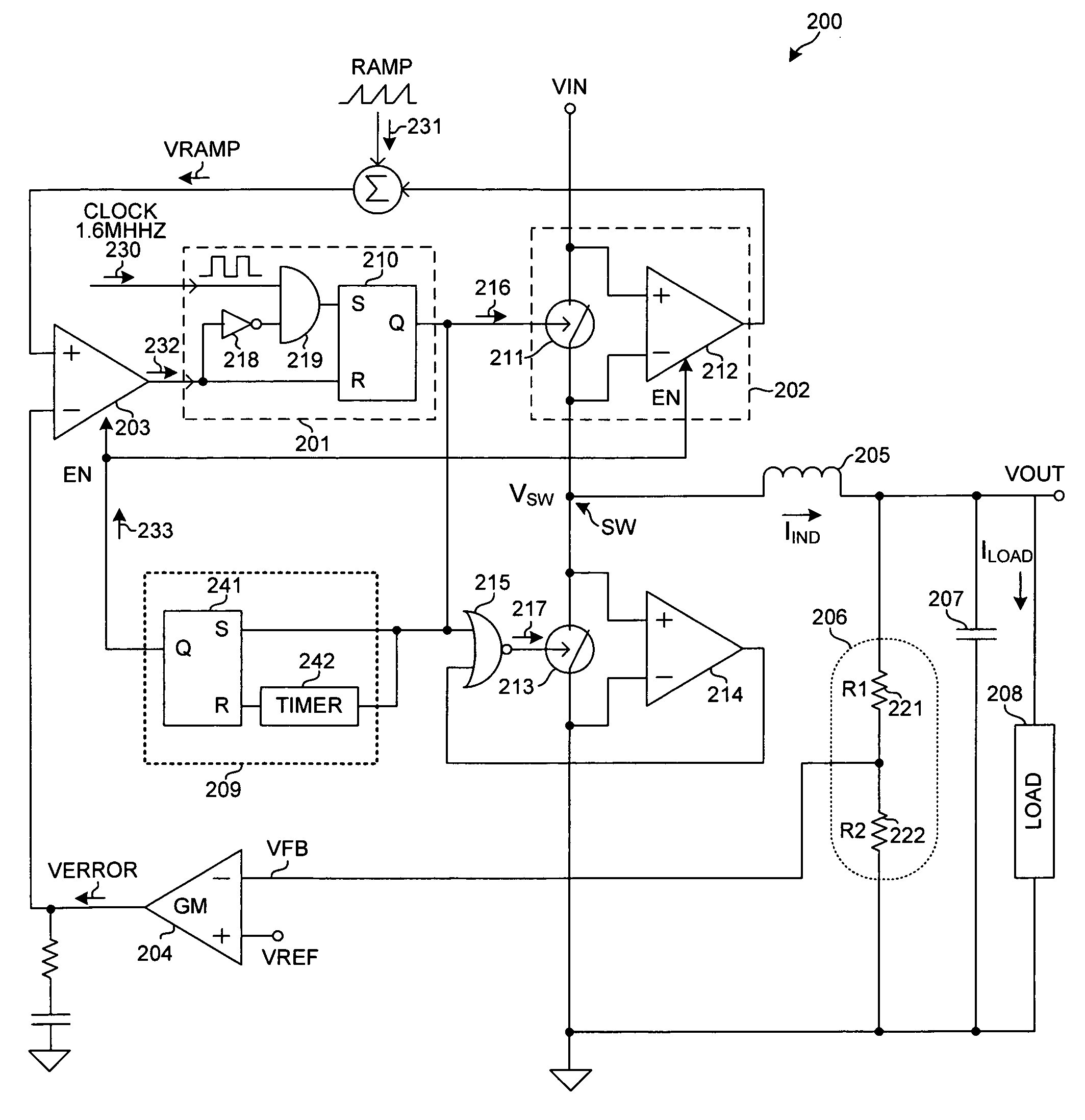
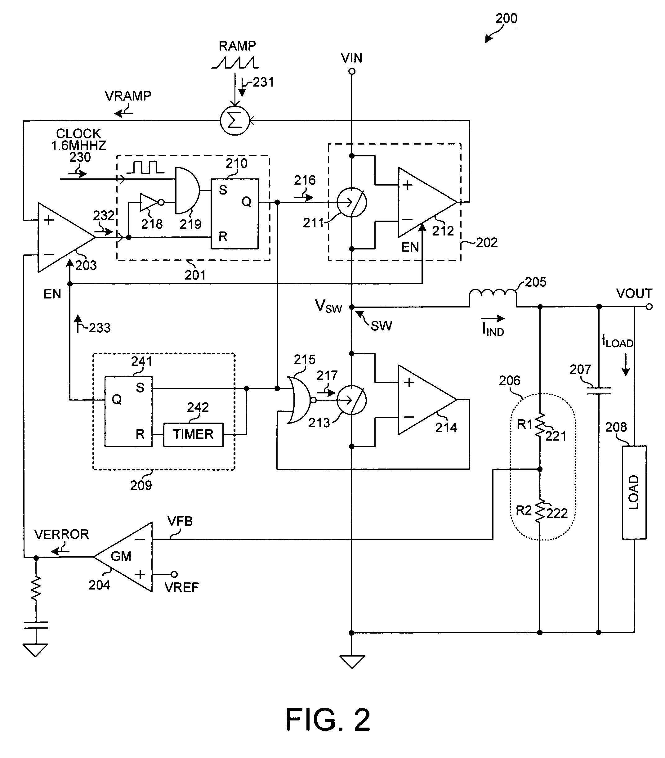
[0014]FIG. 2 is a block diagram of a DC-to-DC converter 200 in accordance with one novel aspect. DC-to-DC converter 200 includes a Pulse-Width Modulation (PWM) controller 201, a power switch unit 202, a PWM comparator 203, an error amplifier 204, an inductor 205, a voltage divider network 206 formed by resistors 221 and 222, an output capacitor 207, a load 208, and a control signal monitoring circuit 209. PWM controller 201 includes a sequential logic element (for instance, an SR latch circuit) 210, an inverter 218, and an AND gate 219. Power switch unit 202 includes a switch device 211 and a current sense amplifier 212. Control signal monitoring circuit 209 includes a sequential logic element (for instance, an SR latch circuit) 241 and a timer 242. DC-to-DC converter 200 further includes a synchronous rectifier 213, a comparator 214, and a ...


PUM


Abstract

A DC-to-DC converter comprises an error amplifier, a comparator, a PWM controller, a power switch unit, and a control signal monitoring circuit. The PWM controller receives a comparison signal from the comparator and generates a digital control signal that controls the power switch unit such that the DC-to-DC converter supplies a regulated voltage onto a load. The control signal monitoring circuit monitors the digital control signal and detects either a heavy load or a light load condition based on characteristics of the digital control signal. Under the light load condition, the monitoring circuit generates a first enabling signal such that the DC-to-DC controller operates in a power-save mode. Under the heavy load condition, the monitoring circuit generates a second enabling signal such that the DC-to-DC controller operates in a normal operation mode. The DC-to-DC converter consumes substantially less power in the power-save mode than in the normal operation mode.

Description

TECHNICAL FIELD[0001]The disclosed embodiments relate to the field of power conversion, and more specifically, to high efficiency DC-to-DC voltage regulators having pulse-width modulation controllers.BACKGROUND INFORMATION[0002]A DC-to-DC converter is a voltage regulator that converts an input direct current voltage to a regulated output direct current voltage. Among different types of voltage regulators, switching regulators are increasing in popularity because they offer higher power conversion efficiency and design flexibility. A switching regulator typically uses a power switch, an inductor, and a diode to transfer energy from input to output. A feedback and control mechanism is used to provide a regulated output voltage. The most commonly used feedback and control mechanism is pulse-width modulation (PWM).[0003]FIG. 1 (Prior Art) is a block diagram of a DC-to-DC converter 100 that generates a regulated output voltage VOUT. DC-to-DC converter 100 includes a PWM controller 101, a...

Claims


Application Information

Patent Timeline
IPC IPC(8): G05F1/00
CPCH02M3/156Y02B70/16H02M2001/0032H02M1/0032Y02B70/10
Inventor GAN, GE
Owner ACTIVE SEMI
Why Eureka
Try Eureka