Polycrystalline silicon reactor

a polycrystalline silicon and reactor technology, applied in the direction of silicon compounds, lighting and heating apparatus, furnaces, etc., can solve the problems of affecting the stability of the reaction, so as to achieve stable production of polycrystalline silicon and strong adhesion of polycrystalline silicon

Active Publication Date: 2009-09-24
HIGH-PURITY SILICON CORP
View PDF8 Cites 20 Cited by
  • Summary
  • Abstract
  • Description
  • Claims
  • Application Information

AI Technical Summary

Benefits of technology

[0017]By virtue of providing concavo-convex portions on the seed rod holding electrode, it is possible to make strong adhesion of the polycrystalline silicon to the seed rod holding electrode. Therefore, even if the reaction takes a long time, cracks or peeling off in the adjacent of the lower ends is suppressed, and then a stable production of the polycrystalline silicon can be performed.
[0018]According to the polycrystalline silicon re

Problems solved by technology

Therefore, the silicon may be peeled off from the electrodes due to its own weight, and may damage the furnace bottom of the reactor.
In addition, the peeled-off po

Method used


Image

  • Polycrystalline silicon reactor
  • Polycrystalline silicon reactor
  • Polycrystalline silicon reactor

Examples


second embodiment

[0050]Next, an electrode 20 in the invention will be described with reference to a drawing.

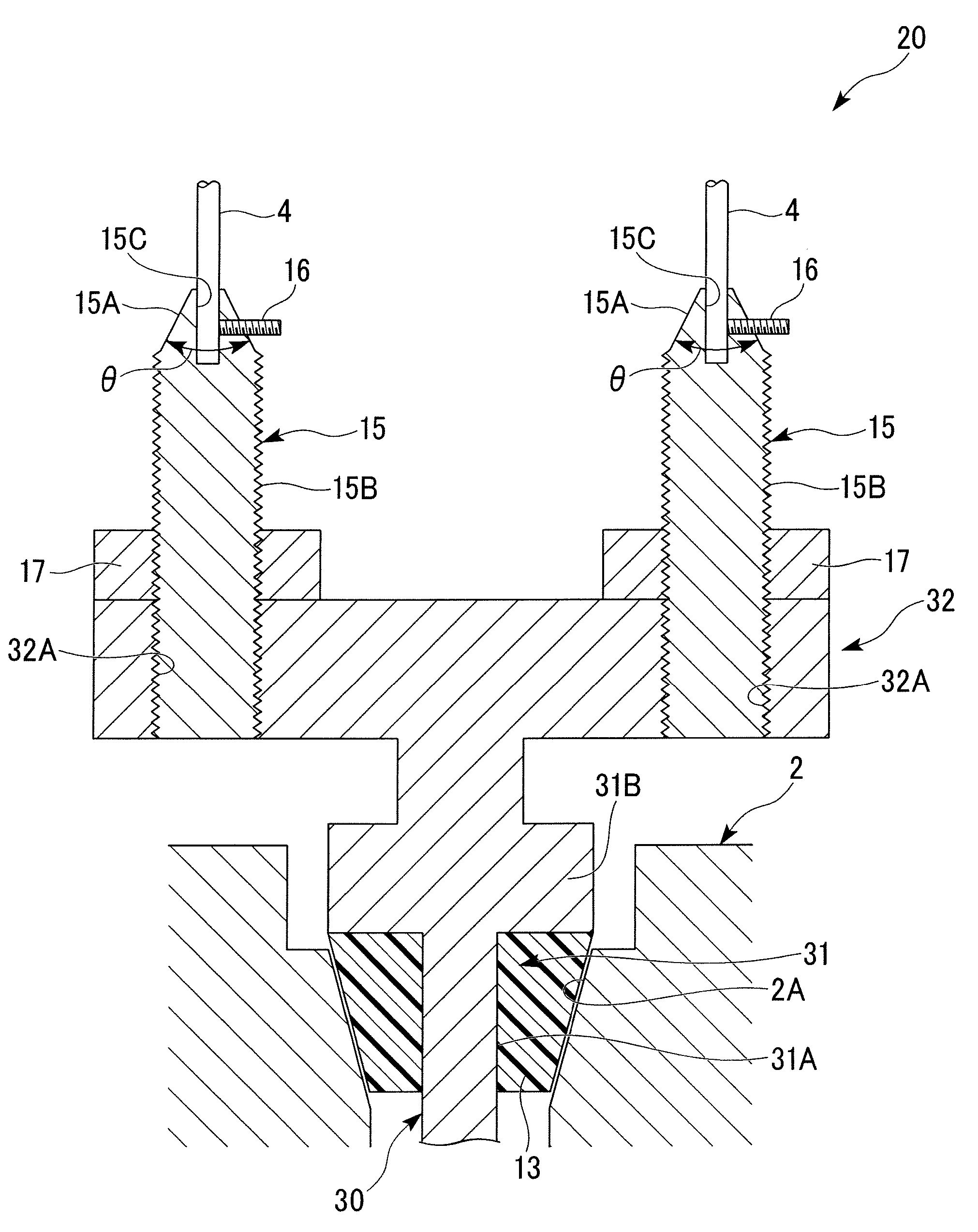
[0051]FIG. 3 is a longitudinal sectional view of an electrode 20 of a polycrystalline silicon reactor according to a second embodiment. The electrode 20 of this embodiment is different from the first embodiment in that the electrode is a so-called double holder type electrode 20 which supports two silicon seed rods 4, 4, while the electrode 5 in the first embodiment supports the single silicon seed rod 4. In addition, the same components in FIG. 3 as those of the first embodiment shown in FIG. 2 will be denoted by the same reference numerals, and a detailed description thereof will be omitted.

[0052]The electrode holder 30 is made of a corrosion-resistant material such as a stainless, hastelloy (registered trademark), has a stood portion 31 which extends in a vertical direction, and a supporting portion 32 which extends horizontally of the stood portion 31 at an upper end of the stood portion 3...

first embodiment

[0056]Similarly to the first embodiment, the seed rod holding electrodes 15 are mounted with lock nuts 17, respectively, fixing seed rod holding electrodes 15 firmly to the supporting portion 32.

[0057]Even in such an electrode 20 of the second embodiment, the same functions and effects as the electrode 5 of the first embodiment are accomplished. Additionally, since the electrode holder 30 is formed in a T-shape and can support the two seed rod holding electrodes 15, it becomes possible to effectively utilize a space in the furnace and to efficiently install the silicon seed rods 4.

[0058]Although the embodiments of the polycrystalline silicon reactor and the method of producing the polycrystalline silicon that are the invention have been described hitherto, the invention is not limited thereto, and can be suitably changed without departing from the technical idea thereof.

[0059]For example, although the taper portion of the seed rod holding electrodes is a flat surface in circular con...


PUM

PropertyMeasurementUnit
Angleaaaaaaaaaa
Angleaaaaaaaaaa
Digital informationaaaaaaaaaa

Abstract

A polycrystalline silicon reactor 1 which can prevent polycrystalline silicon which deposits on the surface of an electrode 5 holding a silicon seed rod 4 from being peeled off is provided. In a polycrystalline silicon reactor 1 which applies an electric current to a silicon seed rod 4 provided within a furnace, thereby heating the silicon seed rod 4, brings a source gas supplied into the furnace into reaction, and deposits polycrystalline silicon on the surface of the silicon seed rod 4, the reactor includes, at a bottom plate 2 (furnace bottom) of the furnace, an electrode holder 10 provided so as to be electrically insulated from the bottom plate 2 (furnace bottom), and a seed rod holding electrode 15 connected to the electrode holder 10, and holding the silicon seed rod 4 toward the upside. Concavo-convex portions (male thread portion) 15B exposed to a furnace atmosphere is provided at an outer peripheral surface of the seed rod holding electrode 15.

Description

BACKGROUND OF THE INVENTION[0001]1. Field of the Invention[0002]The present invention relates to a polycrystalline silicon reactor to be used when producing polycrystalline silicon by the Siemens method.[0003]Priority is claimed on Japanese Patent Application No. 2008-074469, filed Mar. 21, 2008, the content of which is incorporated herein by reference.[0004]2. Description of Related Art[0005]The Siemens method is known as a method of producing high-purity polycrystalline silicon to be used as a semiconductor material. This Siemens method is a production method of bringing a source gas composed of a mixed gas of chlorosilanes and hydrogen into contact with a heated silicon seed rod, and depositing the polycrystalline silicon on the surface of the seed rod by reaction of the source gas. As an apparatus which carries out this production method, a polycrystalline silicon reactor in which many silicon seed rods are stood is used. Generally, the silicon seed rods are connected by a conne...

Claims


Application Information

Patent Timeline
IPC IPC(8): H05B6/10H05B6/02
CPCC01B33/035F27B14/06
Inventor ENDOH, TOSHIHIDETEBAKARI, MASAYUKIISHII, TOSHIYUKISAKAGUCHI, MASAAKI
Owner HIGH-PURITY SILICON CORP
Why Eureka
Try Eureka