Injection device for die casting machine

a technology of injection device and die casting machine, which is applied in the direction of mould control device, manufacturing tool,foundry moulding apparatus, etc., can solve the problems of limiting the reduction in size and weight of electric mechanism, affecting the production efficiency of injection system, and increasing speed, so as to reduce the necessary maximum torque, reduce the manufacturing cost of injection system, and reduce the size of injection system itself.

Inactive Publication Date: 2009-10-01
UBE MASCH CORP LTD
View PDF0 Cites 22 Cited by
  • Summary
  • Abstract
  • Description
  • Claims
  • Application Information

AI Technical Summary

Benefits of technology

[0065]According to the present invention, in a hydraulic circuit of a hybrid injection system of a die casting machine in which a pressure-increasing step for increasing pressure of molten metal for injection pressure and a pressure-holding step for holding pressure of molten metal after the pressure-increasing step are performed electrically, by providing, for example, a switching valve capable of communicating the pressure in an injection cylinder head chamber to a booster rod chamber at the pressure-holding step, the need to keep a large current flowing at the pressure-holding step is avoided by reducing the necessary maximum torque of a servo motor that drives a booster piston rod and the occurrence of a large electric power loss can be prevented and the motor size can be reduced. Because of this, it is possible to reduce the manufacturing cost of an injection system as well as reducing the size of the injection system itself.
[0066]By further comprising the pressure detection sensor (37) for detecting a head pressure, that is, the pressure in the head chamber (16H) of the injection cylinder (16), the torque of the electric motor (1) can be controlled so that the head pressure becomes a predetermined value by detecting the head pressure, and therefore, stable and accurate injection molding is enabled. Furthermore, it is possible to prevent an undesired operation, such as increasing the injection pressure excessively, by performing

Problems solved by technology

In the conventional injection system in which the injection plunger is controlled by an electric mechanism and a hydraulic mechanism, one of factors that impede the further reduction in size and weight, and an increase in speed, is the adoption of a back-and-forth movement structure by the electric mechanism, in which the i

Method used


Image

  • Injection device for die casting machine
  • Injection device for die casting machine
  • Injection device for die casting machine

Examples


second embodiment

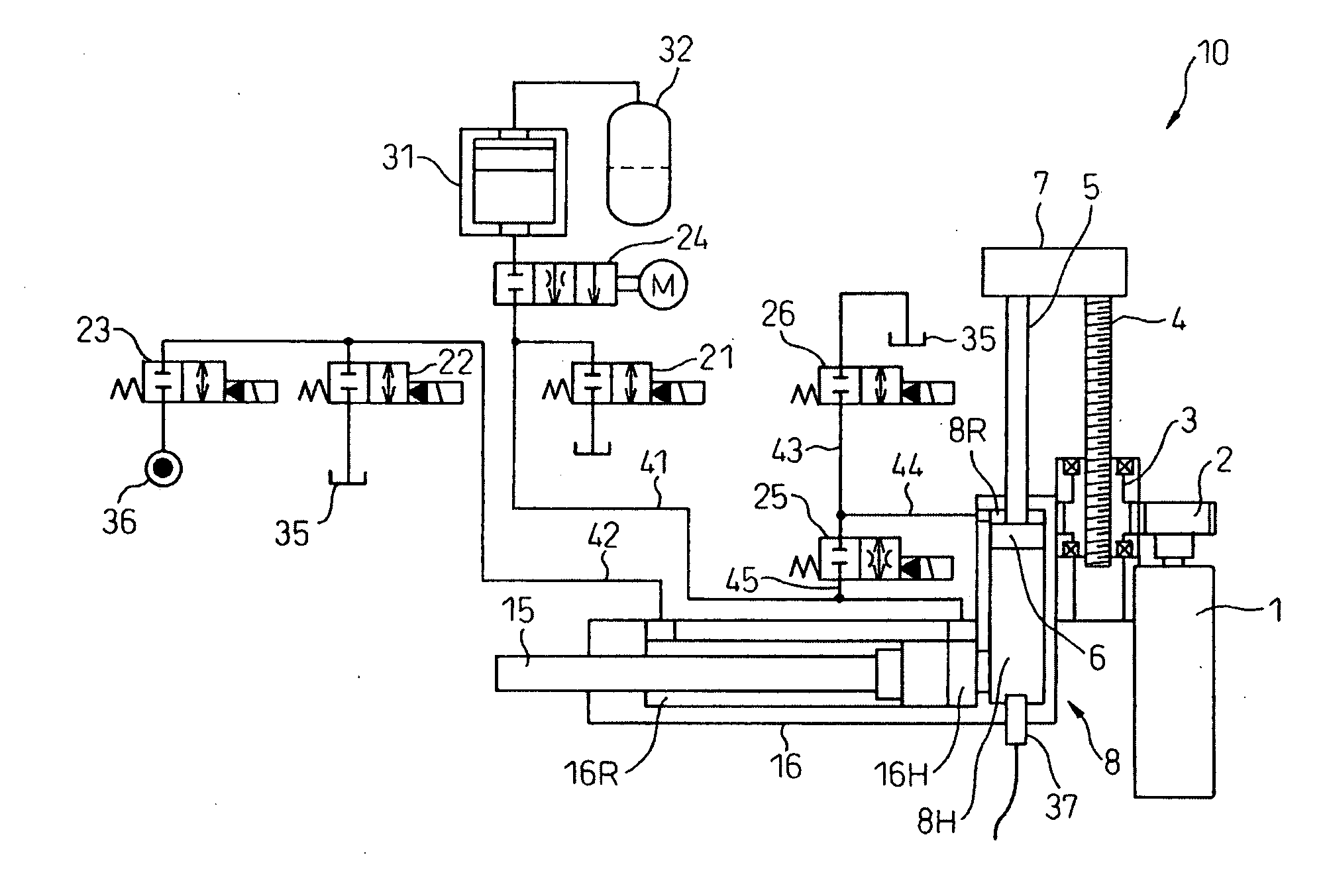
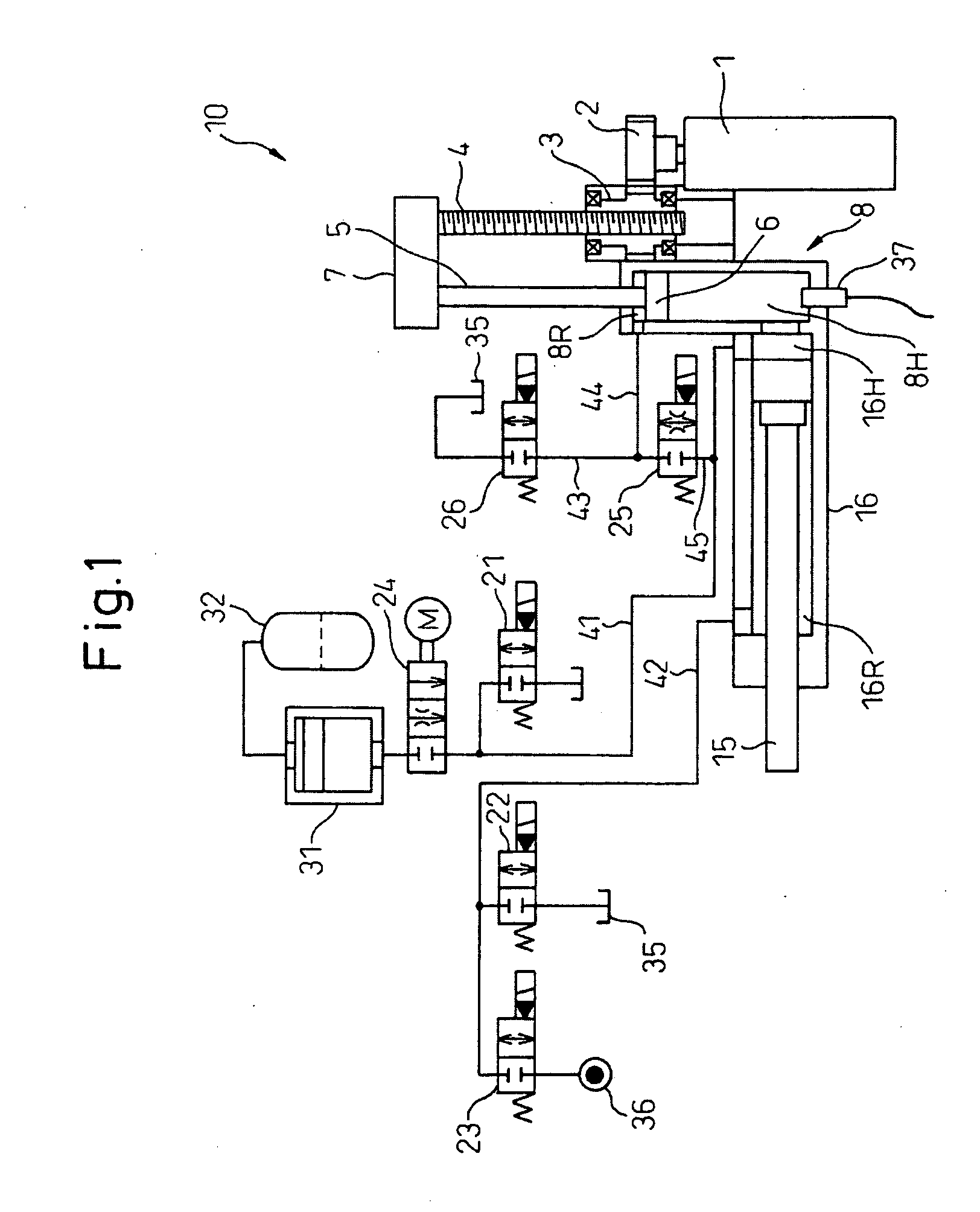
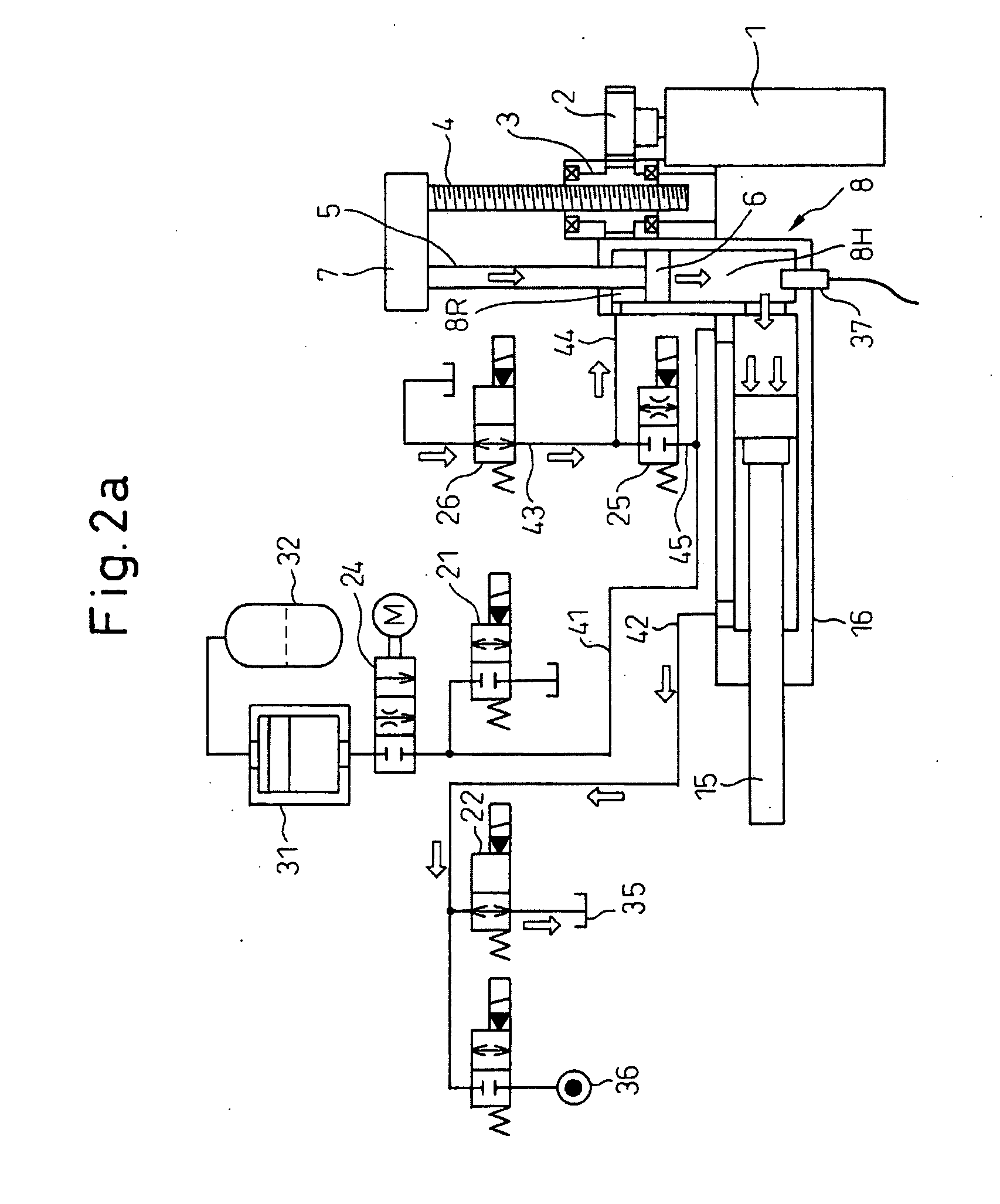
[0128]Next, an injection system 100 for a die casting machine in a second embodiment of the present invention is explained. FIG. 7 and FIGS. 8a to 8g show the injection system 100 for a die casting machine according to the second embodiment of the present invention, wherein FIG. 7 is an explanatory diagram showing a general configuration of a hydraulic circuit in the second embodiment of the injection system for a die casting machine, and FIGS. 8a to 8g are explanatory diagrams showing a state of the hydraulic circuit in various working processes in a die casting machine, The constituent parts in FIG. 7 and FIGS. 8a to 8g that are the same as or similar to the constituent parts in the first embodiment shown in FIG. 1 and FIGS. 2a to 2f are designated by the same reference symbols.

[0129]In the first embodiment, there is no description of the leak of hydraulic oil from the injection piston accumulator 31 (that is, the leak through the valve M 24), and no explanation is given as to the...


PUM

PropertyMeasurementUnit
Timeaaaaaaaaaa
Pressureaaaaaaaaaa
Flow rateaaaaaaaaaa

Abstract

In a hybrid injection system of a die casting machine, the occurrence of a large electric power loss can be prevented by avoiding a large current at a pressure-holding step and the size of a motor is reduced.
In an injection system comprising an injection cylinder (16) housing an injection piston (15) for injecting molten metal to a mold and an electric booster (8) of hydraulic cylinder type, a head chamber (8H) to the electric booster communicates fluidly with a head chamber (16H) of the injection cylinder, causing a booster piston rod (5) to be housed in the electric booster (8) to move linearly and thus pressing under pressure to move the injection piston to perform injection molding. Because a stop valve (25) is provided in a pipe that causes the head chamber (16H) of the injection cylinder to communicate with a rod chamber (8R) of the booster (8), it is possible for the pressure of the hydraulic oil to act on a head area of the electric booster at a pressure-increasing step for increasing pressure of the molten metal, and for pressure of the hydraulic oil to act on a rod area of the electric booster at a pressure-holding step for holding pressure of the molten metal.

Description

CROSS-REFERENCE TO RELATED APPLICATIONS[0001]The present invention claims patent based on the priority of Japanese Patent Application No. 2006-25402 filed on Sep. 20, 2006, Japanese Patent Application No. 2006-324000 filed on Nov. 30, 2006, and Japanese Patent Application No. 2007-143347 filed on May 30, 2007 and these contents are incorporated herein as reference and continued in the subject application.BACKGROUND OF THE INVENTION[0002]1. Field of the Invention[0003]The present invention relates to an injection system of a die casting machine, etc., and more particularly, to a hybrid injection system.[0004]2. Description of the Related Art[0005]In a die cast molding of aluminum alloy, etc., a hydraulic die casting machine in which an injection piston (plunger) is driven by a hydraulic cylinder is used conventionally. In such a die casting machine of this type, the speed and pressure of the injection piston are controlled by controlling the pressure and flow rate of hydraulic oil to...

Claims


Application Information

Patent Timeline
IPC IPC(8): B22D17/00B22D17/32B22C19/04B22D17/04
CPCB22D17/10B22D17/32B22D17/2015B22D17/2023
Inventor UCHIDA, MASASHIHIRAIZUMI, KAZUKI
Owner UBE MASCH CORP LTD
Why Eureka
Try Eureka