Power recovery chamber

Active Publication Date: 2009-10-01
EBARA CORP
View PDF10 Cites 17 Cited by
  • Summary
  • Abstract
  • Description
  • Claims
  • Application Information

AI Technical Summary

Benefits of technology

[0057]The present invention has been made in view of the above problems in the art. It is therefore an object of the present invention to provide a power recovery chamber, for use in a positive-displacement power recovery apparatus utilized in a seawater desalination system, in which wear caused by friction in the powe

Problems solved by technology

The largest operational cost (electric expenses) in the seawater desalination plant is energy cost for pressurizing the pretreated seawater up to such a pressure as to overcome the osmotic pressure, i.e. up to the reverse osmosis pressure.
That is, the operational cost of the seawater desalination plant depends heavily on pressuring energy of the seawater by the high-pressure pump.
Specifically, more than half of the electric expenses as the highest cost in the seawater desalination plant are consumed to operate the high-pressure pump for pressuring the seawater.
(1) In the conventional power recovery chamber, the outer circumferential surface of the piston is brought into sliding contact with the inner circumferential surface of the cylinder. In particular, in the power recovery chamber formed for the purpose of processing the large flow rate, the area of the sliding surface of the piston (in proportion to the diameter of the piston) and the range of reciprocating motion of the piston (stroke) become large. As an example of the dimension of the power recovery chamber, the inner diameter of the cylinder (≈ outer diameter of the piston) is about 0.4 m, and the length of the chamber is about 7 m. As is apparent from this example, the power recovery chamber is large in size, and it is highly likely that frictional wear (wear caused by friction) is generated in one of the sliding surfaces of the cylinder and the piston or both of the sliding surfaces of the cylinder and the piston.
The increase of the friction loss causes a decrease of pressure rising of the seawater in the power recovery chamber, and thus the required energy recovery efficiency cannot be obtained.
Specifically, in the conventional power recovery chamber, trade-off (antinomic phenomenon) between the sliding velocity V and the sliding area A cannot be solved, and thus the problems described in the above (1) and (2) are presented under existing circumstances.
However, because there is “relation 3”, even if the sliding area A becomes small, the problem of “friction” cannot be improved.
Accordingly, abrasion powder of one of the cylinder and the piston or both of the cylinder and the piston produced by the above frictional wear enters constituent equipment of the system,

Method used


Image

  • Power recovery chamber
  • Power recovery chamber
  • Power recovery chamber

Examples


Example

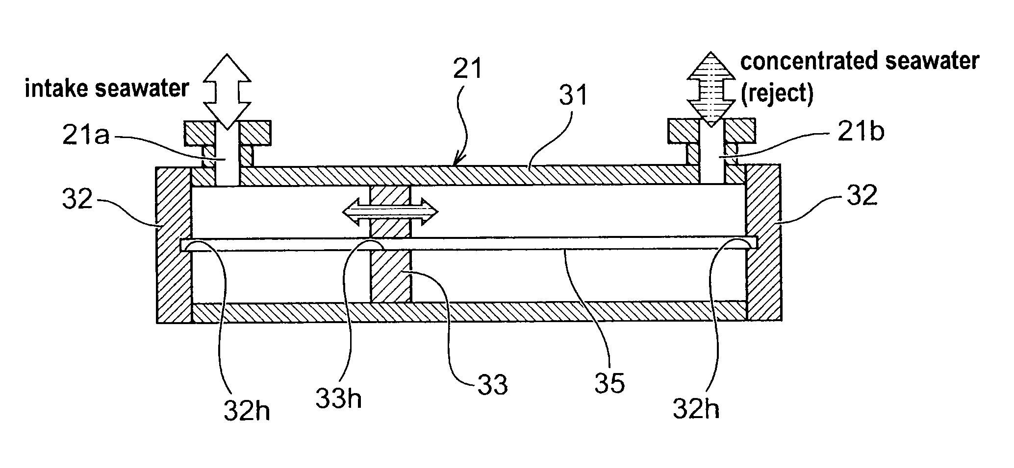
[0131]FIGS. 4A and 4B are views showing a power recovery chamber according to a first embodiment of the present invention. FIG. 4A is a perspective view of the power recovery chamber, and FIG. 4B is a schematic cross-sectional view of the power recovery chamber. As shown in FIGS. 4A and 4B, the power recovery chamber 21 comprises a cylinder 31 having a cylindrical shape, circular cylinder covers 32, 32 for covering both opening ends of the cylinder 31, a piston 33 which is reciprocated in the cylinder 31, and a piston guide 35 provided between the cylinder covers 32, 32 and extending through the central part of the cylinder 31. The piston guide 35 has both ends which are fixed to the centers of the cylinder covers 32 so that the piston guide 35 is located on a central axis of the cylinder 31. Each of the circular cylinder covers 32 has a hole 32h for fixing the piston guide 35 at the central part of the cylinder cover 32, and each end of the piston guide 35 is fitted into the hole 3...

Example

[0139]FIGS. 7A and 7B are views showing a power recovery chamber according to a second embodiment of the present invention. FIG. 7A is a schematic cross-sectional view of the power recovery chamber, and FIG. 7B is an enlarged view of VII part of FIG. 7A. As shown in FIGS. 7A and 7B, the power recovery chamber according to the second embodiment of the present invention is different from the power recovery chamber according to the first embodiment of the present invention in the configuration of piston. As shown in FIGS. 7A and 7B, in the piston 33 according to the second embodiment, a piston bearing 36 constituting a sliding member is provided on a sliding surface sliding against the piston guide 35. As a method for fixing the piston bearing 36 to the piston 33, adhesive bonding, shrink fitting, cooled fitting, screw cramp, or other measures may be used. In short, if the piston bearing 36 is fitted in the central axis part of the piston 33 and fixed thereto, any method may be used.

[0...

Example

[0152]According to the third embodiment of the present invention, because the radial clearance between the inner surface of the cylinder 31 and the outer surface of the flange part (piston flange) 33f becomes small, the contact interface between the concentrated seawater and the intake seawater becomes small. Therefore, the mixed quantity of the concentrated seawater and the intake seawater is very small, and the above problem (5) can also be suppressed. Thus, the freshwater recovery rate of the reverse osmosis membrane can be prevented from being lowered, the service life of the reverse osmosis membrane cartridge can be prevented from being shortened, and the operational efficiency of the seawater desalination system can be prevented from being lowered.


PUM

PropertyMeasurementUnit
Thicknessaaaaaaaaaa
Pressureaaaaaaaaaa

Abstract

A power recovery chamber is used for a positive-displacement power recovery apparatus in the seawater desalination plant or system. The power recovery chamber includes a cylinder, a piston disposed in the cylinder and capable of being reciprocated in a longitudinal direction of the cylinder, and a piston guide disposed in the cylinder and extending in the longitudinal direction of the cylinder for guiding the piston when the piston is reciprocated in the longitudinal direction of the cylinder. At least a part of an outer circumferential surface of the piston is out of contact with an inner surface of the cylinder, and the piston is brought into contact with the piston guide at a part where the piston guide passes through the piston.

Description

BACKGROUND OF THE INVENTION[0001]1. Field of the Invention[0002]The present invention relates to a power recovery apparatus for use in a seawater desalination plant or a seawater desalination system for desalinating seawater by removing salinity from the seawater. Particularly, the present invention relates to a power recovery chamber which is preferably used for a positive-displacement power recovery apparatus in the seawater desalination plant or system, can improve reliability of the seawater desalination plant or system, can operate the seawater desalination plant or system at high efficiency (energy-saving), and can recover fresh water by the seawater desalination plant or system at high efficiency.[0003]2. Description of the Related Art[0004]A seawater desalination plant which employs a reverse osmosis membrane method is composed mainly of a pretreatment system, a high-pressure pump, a reverse osmosis membrane cartridge, and a power recovery apparatus. When seawater is introdu...

Claims


Application Information

Patent Timeline
IPC IPC(8): C02F1/44F04B17/00F04B35/02B01D61/06
CPCB01D61/025C02F2103/08C02F1/441B01D61/06Y02A20/131
Inventor SHINODA, MASAOHOSHINO, KENICHIGOTO, AKIRAKANNO, HIDEKI
Owner EBARA CORP
Why Eureka
Try Eureka