
Hydraulic Control System for Multi-Mode Hybrid Transmission and Method of Regulating the Same

a hybrid-type power transmission and hydraulic control technology, which is applied in fluid gearings, transportation and packaging, gearing, etc., can solve the problems of affecting the reliability and durability of the transmission, hydraulic pumps which derive their power solely from the engine may become inoperable, and the packaging space in and around the powertrain of hybrid-type vehicles is normally scarce, so as to improve the efficiency and reliability of the vehicle powertrain. , the effect of improving the response tim

Active Publication Date: 2009-10-01
GM GLOBAL TECH OPERATIONS LLC
View PDF6 Cites 41 Cited by
  • Summary
  • Abstract
  • Description
  • Claims
  • Application Information

AI Technical Summary

Benefits of technology

[0011]The present invention provides an improved hydraulic control system for a multi-mode hybrid-type power transmission. In order to enhance the efficiency, reliability, and response time of the vehicle powertrain, the present invention also provides improved methods of operating the hydraulic control system. The methods of the present invention ensure continuous clutch pressure at specific controlled levels during all vehicle operations, including engine auto-start and auto-stop, and transitionary periods thereto. In doing so, the present invention protects against pressure drops during pump transitions and pressure handoffs that might otherwise cause a clutch slip or bump. This invention also protects the auxiliary pump from high transmission pressures by providing additional pressure exhaust paths and a boost accumulator valve.
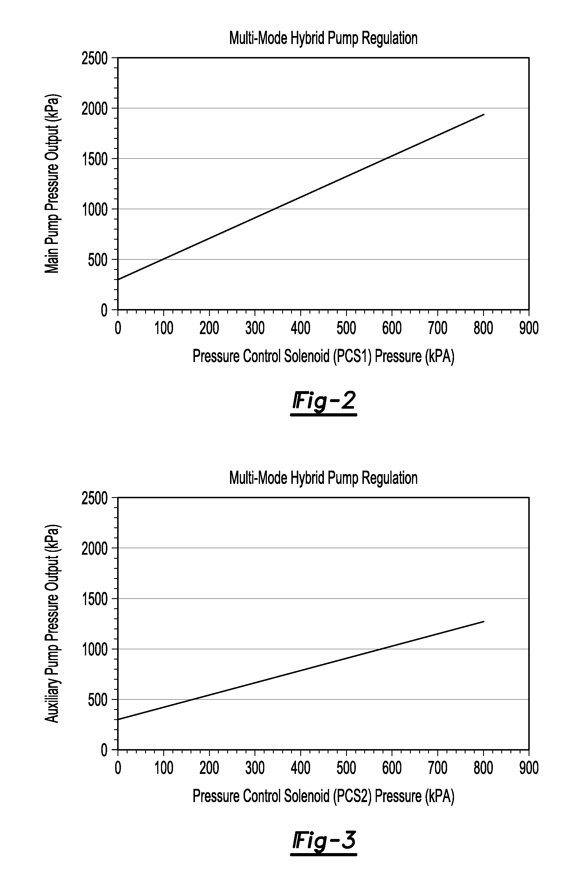
[0014]According to one aspect of this embodiment, setting the start-up auxiliary pump pressure equal to a minimum auxiliary pump pressure includes closing the pressure control solenoid, and thereby eliminating boost pressure distributed to the auxiliary regulator valve from the pressure control solenoid.
[0015]It is desired that the method of this embodiment also includes reducing the current main pump pressure to equal a minimum main pump pressure prior to stopping the main pump if the engine is transitioning to an engine auto-stop. Reducing the current main pump pressure preferably includes closing an additional pressure control solenoid that is in fluid communication with the main regulator valve, and thereby eliminating boost pressure distributed to the main regulator valve from the pressure control solenoid that is in fluid communication with the main regulator valve.
[0017]It is further desired that the method includes: determining if the engine is transitioning to an engine auto-start; determining the current line pressure requirements of the transmission if the engine is transitioning to an engine auto-start; setting the start-up pressure of the main pump equal to an optimal main pump start-up pressure; starting the main pump; increasing the speed of the main pump; modifying the current pressure of the main pump to equal the current line pressure requirements by providing a boost pressure to the main regulator valve with the additional pressure control solenoid that is in fluid communication therewith; and stopping the auxiliary pump. By utilizing a separate pressure control solenoid for pressure regulation and boost function operation, the output of each pump can be individually optimized under all vehicle operating conditions. Moreover, this invention allows both pumps to be on at the same time at any desired pressure by using independent line pressure control for each.
[0018]In this instance, setting the main pump start-up pressure equal to an optimal main pump start-up pressure preferably includes commanding the pressure control solenoid to distribute a predetermined optimal boost gain pressure to the main regulator valve. It is further preferred that the method also includes reducing the current pressure of the auxiliary pump to equal the minimum auxiliary pump pressure prior to stopping the auxiliary pump. The auxiliary pump pressure can be reduced by closing the respective pressure control solenoid, and thereby eliminating boost pressure distributed to the auxiliary regulator valve by the pressure control solenoid in communication therewith. Finally, stopping the auxiliary pump is preferably in response to the current main pump pressure being equal to the current line pressure requirements of the transmission.

Problems solved by technology

The lubricating and cooling capabilities of transmission oil systems greatly impact the reliability and durability of the transmission.
When the engine in a hybrid-type vehicle is not operating (i.e., in a power-off state), hydraulic pumps which derive their power solely from the engine may become inoperable.
Packaging space in and around the powertrain in hybrid-type vehicles is normally scarce, often restricting use of a larger auxiliary pump motor.
In addition to architectural limitations, installing a larger pump motor is not always possible due to mass, cost, and fuel economy constraints.
As such, the motor of a transmission auxiliary pump may be so small that it may not be able to start reliably under certain conditions.
However, a transmission auxiliary pump which fails during transition periods (e.g., transition to hybrid “engine-off driving mode”) can potentially result in slip in the transmission launching clutch, and may result in “engine-on” operation only.
Due to size limitations, the auxiliary pump is generally limited in the pressure it can operate against.
As such, the auxiliary pump may stall if it is forced to operate at excessive transmission pressures.

Method used


Image

  • Hydraulic Control System for Multi-Mode Hybrid Transmission and Method of Regulating the Same
  • Hydraulic Control System for Multi-Mode Hybrid Transmission and Method of Regulating the Same
  • Hydraulic Control System for Multi-Mode Hybrid Transmission and Method of Regulating the Same

Examples


Embodiment Construction

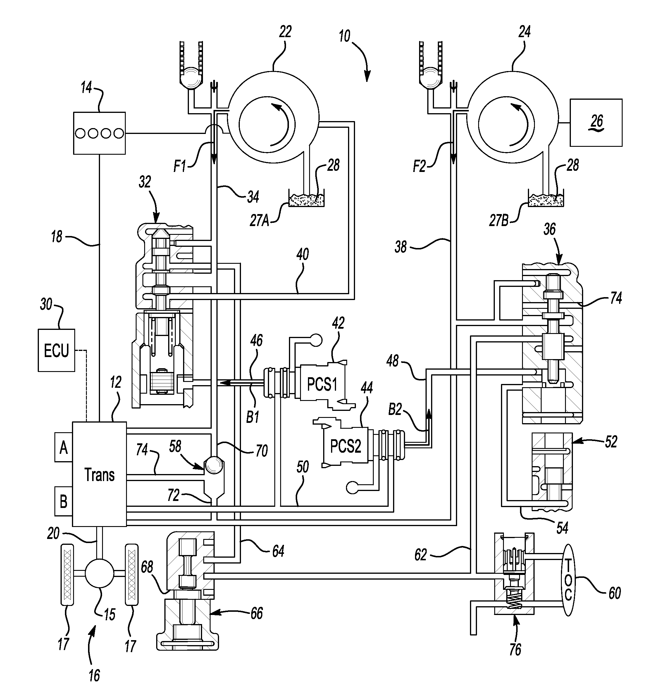
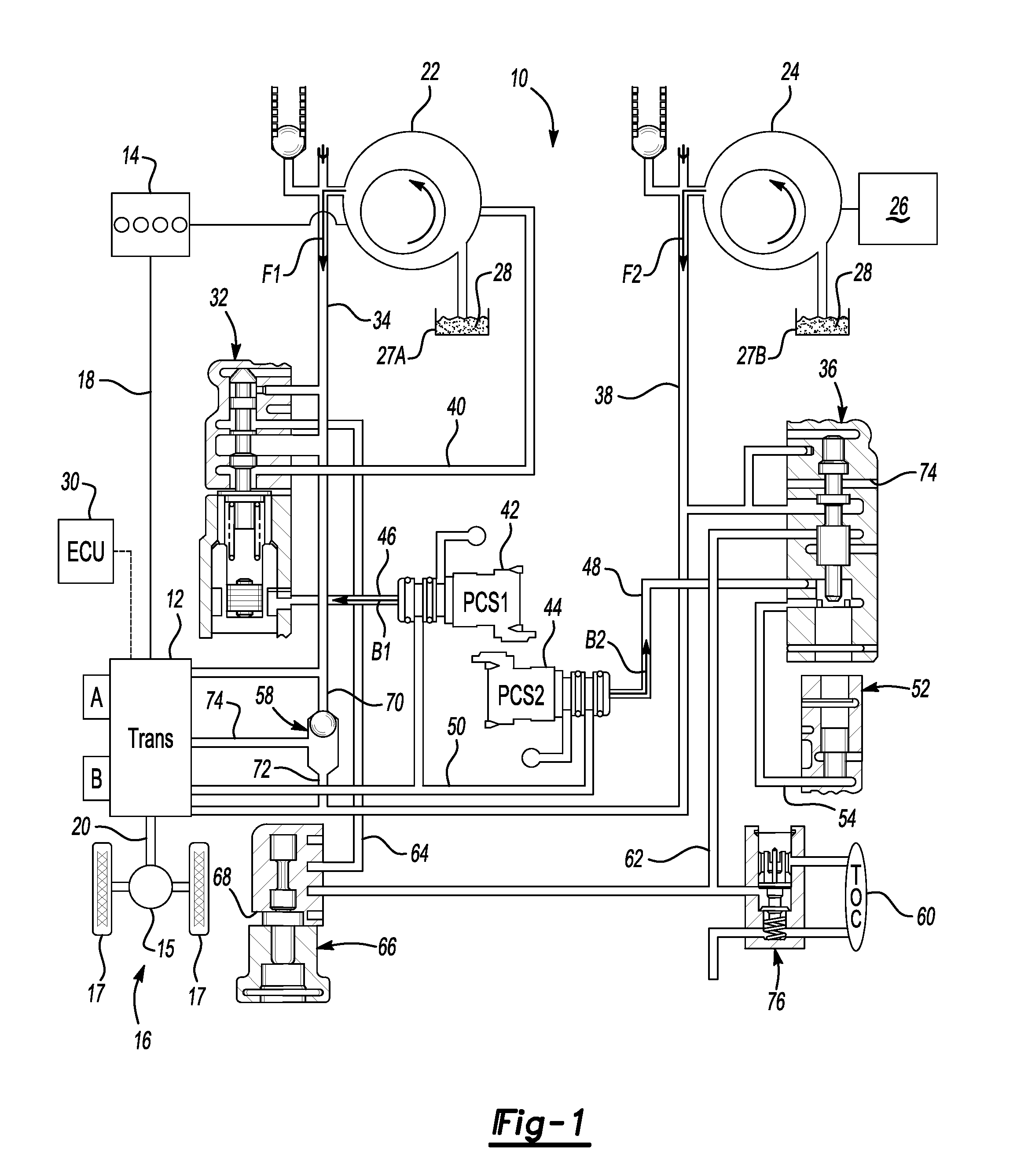
[0032]Referring to the drawings, wherein like reference numbers represent the same or corresponding parts throughout the several views, there is shown schematically in FIG. 1 a hydraulic control system, identified generally as 10, for providing lubrication and cooling fluid to various components of a power transmission 12, as well as pressurized fluid for controlled engagement and disengagement of the various torque transmitting mechanisms that operate to establish the forward and reverse speed ratios within the transmission 12. The hydraulic control system 10, although described herein for supplying hydraulic fluid to a multi-mode hybrid-type power transmission 12 of an automobile, may also be applied in other various applications, such as, by way of example, aeronautical vehicles (e.g., airplanes, helicopters, etc.), agricultural vehicles (e.g., combine, tractor, etc.), construction vehicles (e.g., forklift, backhoe, excavator, etc.), and stationary machines (e.g., hydraulic press...


PUM


Abstract

A hydraulic control system for a multi-mode hybrid-type power transmission is provided, including an engine-driven main pump in fluid communication with a main regulator valve, and an electrically driven auxiliary pump in fluid communication with an auxiliary regulator valve. A first pressure control solenoid is configured to provide boost pressure to the main regulator valve and thereby boost output of the main pump. A second pressure control solenoid is configured to provide boost pressure to the auxiliary regulator valve and thereby boost output of the auxiliary pump. The distribution of boost pressure from the pressure control solenoids is selectively modified such that at least one of the flows of pressurized fluid from the pumps is equal to the current line pressure requirements of the transmission during engine auto-start and auto-stop, and transitions thereto. An improved method for regulating the hydraulic control system is also provided.

Description

CLAIM OF PRIORITY AND CROSS-REFERENCE TO RELATED APPLICATION[0001]This application claims the benefit of and priority to U.S. Provisional Patent Application No. 61 / 040,878, filed on Mar. 31, 2008, which is hereby incorporated by reference in its entirety.TECHNICAL FIELD[0002]The present invention relates generally to motorized vehicle powertrains. More specifically, the present invention relates to hydraulic control systems for multi-mode hybrid-type power transmissions, and methods of operating the same.BACKGROUND OF THE INVENTION[0003]In general, motorized vehicles, such as the conventional automobile, include a powertrain that is comprised of an engine in power flow communication with a final drive system (e.g., rear differential and wheels) via a multi-speed power transmission. Hybrid type powertrains generally employ an internal combustion engine (ICE) and one or more motor / generator units that operate individually or in concert to propel the vehicle—e.g., power output from the...

Claims


Application Information

Patent Timeline
Patent Type & Authority Applications(United States)
IPC IPC(8): F16H61/00
CPCF16H61/0031Y10T477/6939Y10T477/631
Inventor TRYON, ERIC S.FOSTER, MICHAEL D.
Owner GM GLOBAL TECH OPERATIONS LLC
Learn More