[0016]an EGR device for recirculating the cooled exhaust gas into the intake air passage of the engine through an EGR valve that controls the recirculating amount of the exhaust gas and a cooler that cools the exhaust gas, and an exhaust gas introduction mechanism which enables the exhaust gas outlet of the engine to be communicated with the cylinders of the engine for a short period of time in the engine intake
stroke;
[0023]The diesel engine of the invention executes the
HCCI combustion by advancing the timing for injecting the fuel into the cylinders in the region of low exhaust gas temperatures and by compressing the fuel in a state where it has been mixed with the air in advance so as to be ignited by compression. In the
HCCI combustion, the
combustion is quickly completed after the ignition, and the unburned component such as PM is little formed. Therefore, the PM is trapped in much reduced amounts by the second continuously regenerating DPF in the region of low exhaust gas temperatures as compared to the ordinary
combustion system in the diesel engine, i.e., as compared to the
diffusion combustion system in which the fuel is injected near the
top dead center so as to be mixed with the air of a high temperature and burns gradually. Therefore, the PM is reliably trapped despite the DPF has a small capacity. Besides, as the temperature of the exhaust gas rises, the oxidizing catalyst in the second continuously regenerating DPF of the small capacity is quickly activated to quickly oxidize and remove the PM that is trapped.
[0024]The
HCCI combustion, generally, involves a difficulty in controlling the
ignition timing for effecting the ignition by compression and causes an early ignition. According to the present invention, on the other hand, the cool EGR controls the amount of the exhaust gas recirculated into the cylinder to normalize the
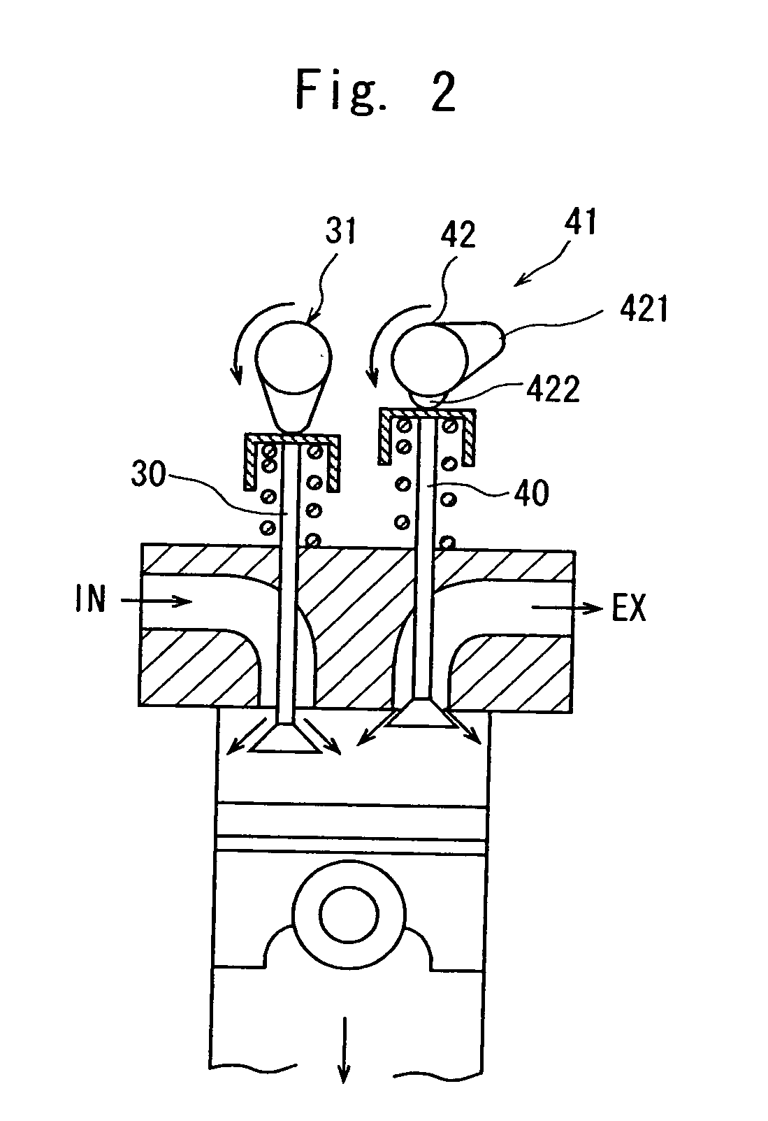
ignition timing. Further, the diesel engine of the present invention is equipped with an exhaust gas introduction
mechanism based on an internal EGR for communicating the exhaust gas outlet with the cylinders of the engine for a short period of time in the engine intake
stroke. The exhaust gas refluxing from the exhaust gas introduction mechanism is the exhaust gas right after the exhaust gas outlet and has a high temperature and contains the combustion
intermediate product. Since the exhaust gas stays near the
cylinder head over the
combustion chamber, the HCCI combustion of the invention promotes the combustion after the premixed mixture is ignited; i.e., executes the combustion forming PM in further reduced amounts.
[0025]According to the diesel engine of the invention as described above, the exhaust gas is recirculated into the cylinders by the cool EGR and is introduced therein by the internal EGR even in the region of low exhaust gas temperatures, suppressing the formation of NOx in the region of low exhaust gas temperatures. Therefore, the urea-added SCR catalyst disposed in the exhaust gas passage of the diesel engine of the invention does not have to be activated in the region of low exhaust gas temperatures saving urea correspondingly that is added while the engine is in operation and making it possible to reduce the amount of urea stored in the urea tank.
[0026]As recited in claim 2, it is desired that the diesel engine employs a common-rail type
fuel injection device and in the region of low exhaust gas temperatures, the timing for injecting the fuel into the diesel engine is set in a range of 30° to 20° ahead of the
top dead center. The common-rail type
fuel injection device injects the fuel from a
fuel storage tube of a
high pressure called
common rail being controlled by an
electromagnetic valve, and makes it possible to correctly control the amount of fuel injected into the diesel engine and the injection timing. When the HCCI combustion is executed in the diesel engine having the EGR device of the present invention, further, the injection timing does not have to be very advanced but may be suitably set in a range of 30° to 20° ahead of the
top dead center.
[0029]As recited in claim 5, the diesel engine has an intake air
shutter and an exhaust gas
shutter disposed in the intake air passage and in the exhaust gas passage, and in the region of low exhaust gas temperatures, the opening degrees of the intake air
shutter and of the exhaust gas shutter are decreased to squeeze the intake air passage and the exhaust gas passage. Therefore, the excess air ratio of the engine decreases, the temperature of the exhaust gas increases, and the second continuously regenerating DPF disposed in the by-path can be quickly activated. As recited in claim 6, further, it is desired to so control that the opening degree of the change-over valve is increased in the regions other than the region of low exhaust gas temperatures, the opening degrees of the intake air shutter and of the exhaust gas shutter are increased to become larger than those in the region of low exhaust gas temperatures in a region of intermediate exhaust gas temperatures where the exhaust gas temperature of the engine is higher than that in the region of low exhaust gas temperatures, and the intake air shutter and the exhaust gas shutter are fully opened in a region of high exhaust gas temperatures where the exhaust gas temperature of the engine is in excess of that in the region of intermediate exhaust gas temperatures. In this case, the amount of the cool EGR for excellently decreasing the NOx can be easily optimized depending upon the region of the exhaust gas temperatures of the diesel engine, i.e., depending upon the operation conditions. By effecting fine control relying upon the cool EGR, intake air shutter and exhaust gas shutter, the amount of NOx can be reduced without adversely affecting the
operability of the engine or the
fuel efficiency.
