Low vt antifuse device

a low-voltage, anti-fuse technology, applied in semiconductor devices, semiconductor/solid-state device details, electrical apparatus, etc., can solve the problems of affecting the proper operation of the single-transistor anti-fuse memory cell, the redesign incurs significant cost overhead, and the leakage of salicided transistors, so as to reduce and achieve the effect of reducing the risk of forming defects

Active Publication Date: 2009-10-08
SYNOPSYS INC
View PDF7 Cites 58 Cited by
  • Summary
  • Abstract
  • Description
  • Claims
  • Application Information

AI Technical Summary

Benefits of technology

[0020]It is an object of the present invention to obviate or mitigate at least one disadvantage of previous anti-fuse memory devices.

Problems solved by technology

It is well known that salicided transistors are known to have higher leakage and therefore lower breakdown voltage.
Unfortunately, foundries for manufacturing semiconductor devices may have set types of LV transistor processes for manufacturing core circuits of the memory device, where the Vt control implant differs depending on the circuit application or function.
Such redesign incurs significant cost overhead, which is necessitated again when the foundry introduces a new generation of the process to accommodate a new manufacturing technology node.
In either case, defects affecting the proper operation of the single transistor anti-fuse memory cell are more likely to be formed.
Another important issue is reliability of the anti-fuse memory device, and more specifically the quality of the thin gate oxide.
Generally, the more process steps that the anti-fuse device is subjected to, the higher the probability for producing a defective anti-fuse device.
Since anti-fuse based memory devices are programmed after manufacture by end-users, it is difficult to test for the reliability of an anti-fuse device before programming.
Therefore the quality of the thin gate oxide should be maximized, since an inadvertently programmed anti-fuse device or an unprogrammable anti-fuse device will likely cause failure in the system.
In the automotive industry, such a failure can have catastrophic consequences.
Accordingly, it is difficult to manufacture a consistently low Vt anti-fuse device with current CMOS processes.

Method used


Image

  • Low vt antifuse device
  • Low vt antifuse device
  • Low vt antifuse device

Examples


Embodiment Construction

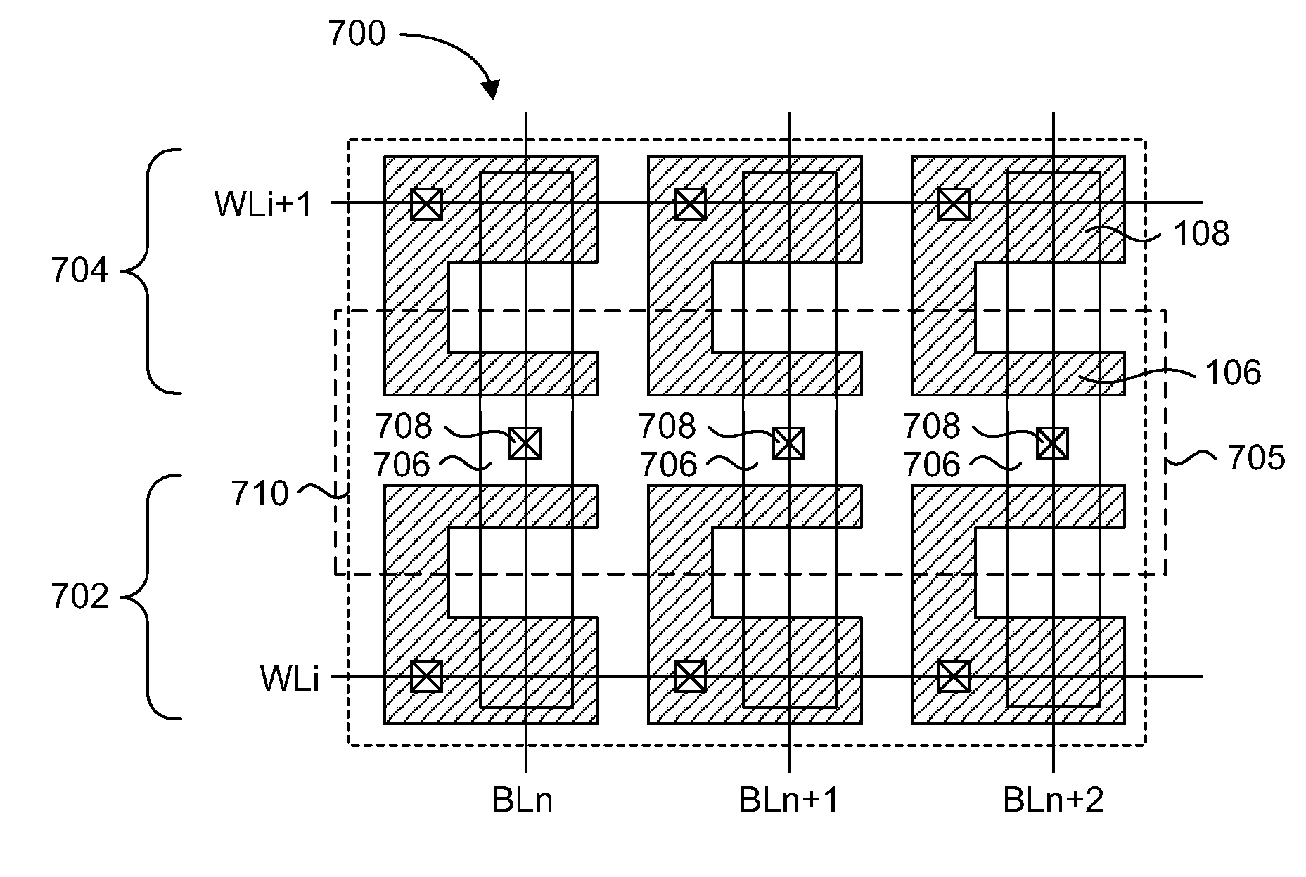
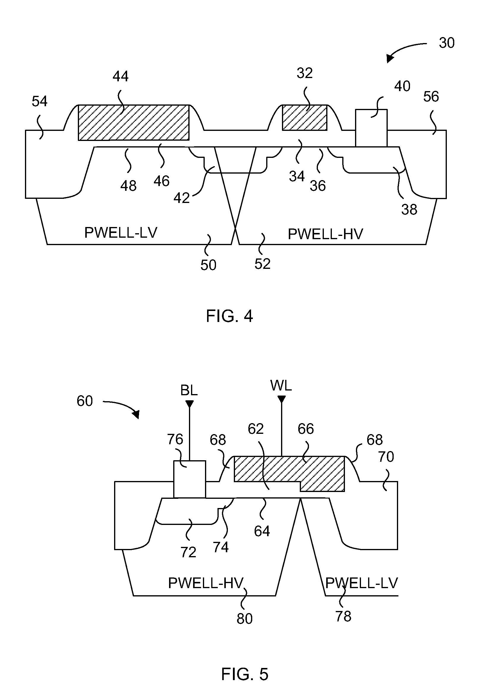
[0046]The embodiments of the present invention describe a one time programmable memory cell having an anti-fuse device with a low threshold voltage independent of core circuit process manufacturing technology. A two transistor memory cell having a pass transistor and an anti-fuse device, or a single transistor split channel memory cell having a dual thickness gate oxide, are formed in a high voltage well that is used for forming high voltage transistors. The threshold voltage of the anti-fuse device differs from the threshold voltages of any transistor in the core circuits of the memory device, but has a gate oxide thickness that is the same as a transistor in the core circuits. The pass transistor has a threshold voltage that differs from the threshold voltages of any core circuit transistor, and has a gate oxide thickness that differs from any transistor in the core circuits.

[0047]In particular, the embodiments of the present invention achieve a low programmed anti-fuse device thr...


PUM


Abstract

A one time programmable memory cell having an anti-fuse device with a low threshold voltage independent of core circuit process manufacturing technology is presented. A two transistor memory cell having a pass transistor and an anti-fuse device, or a single transistor memory cell having a dual thickness gate oxide, are formed in a high voltage well that is formed for high voltage transistors. The threshold voltage of the anti-fuse device differs from the threshold voltages of any transistor in the core circuits of the memory device, but has a gate oxide thickness that is the same as a transistor in the core circuits. The pass transistor has a threshold voltage that differs from the threshold voltages of any transistor in the core circuits, and has a gate oxide thickness that differs from any transistor in the core circuits. The threshold voltage of the anti-fuse device is lowered by omitting some or all of the threshold adjustment implants that is used for high voltage transistors fabricated in the I/O circuits.

Description

CROSS REFERENCE TO RELATED APPLICATIONS[0001]This application claims the benefit of priority of U.S. Provisional Patent Application No. 61 / 042,511 filed on Apr. 4, 2008, which is incorporated herein by reference in its entirety.FIELD OF THE INVENTION[0002]The present invention relates generally to non-volatile memory. More particularly, the present invention relates to anti-fuse devices.BACKGROUND OF THE INVENTION[0003]In the following description the term MOS is used to denote any FET or MIS transistor, half-transistor or capacitor structure. In order to simplify the description of the embodiments, references to gate oxides from this point forward should be understood to include dielectric materials, oxide, or a combination of oxide and dielectric materials.[0004]Over the past 30 years, anti-fuse technology has attracted significant attention of many inventors, IC designers and manufacturers. An anti-fuse is a structure alterable to a conductive state, or in other words, an electro...

Claims


Application Information

Patent Timeline
Patent Type & Authority Applications(United States)
IPC IPC(8): H01L29/76H01L21/82H01L21/44
CPCH01L23/5252H01L27/101H01L27/0207H01L2924/0002H01L29/42368H10B20/20H01L2924/00
Inventor KURJANOWICZ, WLODEK
Owner SYNOPSYS INC
Why Eureka
Try Eureka