
MOSFET Parametric Amplifier

a parametric amplifier and amplifier technology, applied in the field of circuits, can solve the problems of low power, low noise, and large signal amplification, and achieve the effect of low power

Inactive Publication Date: 2009-10-08
THE TRUSTEES OF COLUMBIA UNIV IN THE CITY OF NEW YORK
View PDF13 Cites 8 Cited by
  • Summary
  • Abstract
  • Description
  • Claims
  • Application Information

AI Technical Summary

Benefits of technology

The present invention provides a way to improve the performance of parametric amplifiers by using a parametric amplifier with a MOS capacitor. This combination allows for low-noise, large-signal amplification that was previously not possible with previous techniques. The use of a MOS capacitor makes possible the use of a larger source and drain terminal, which results in a larger signal. The invention also describes the operation of a parametric amplifier and how it can be used in a differential operation. The use of a MOS capacitor and a larger source and drain terminal increases the gain of the amplifier. The invention also discusses the dynamic power dissipation of the amplifier and how it can be minimized. Overall, the invention provides a way to improve the performance of parametric amplifiers and make them more efficient in amplifying signals.

Problems solved by technology

The use of a parametric amplifier makes very low power, low-noise, large-signal amplification possible, which was not possible with earlier techniques.
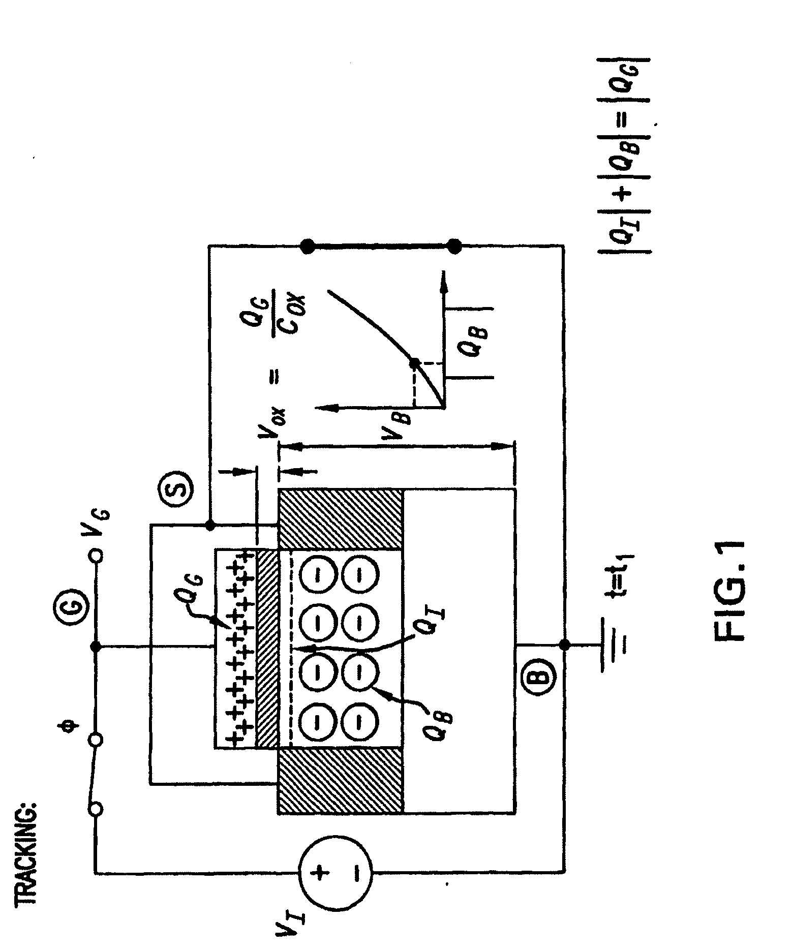
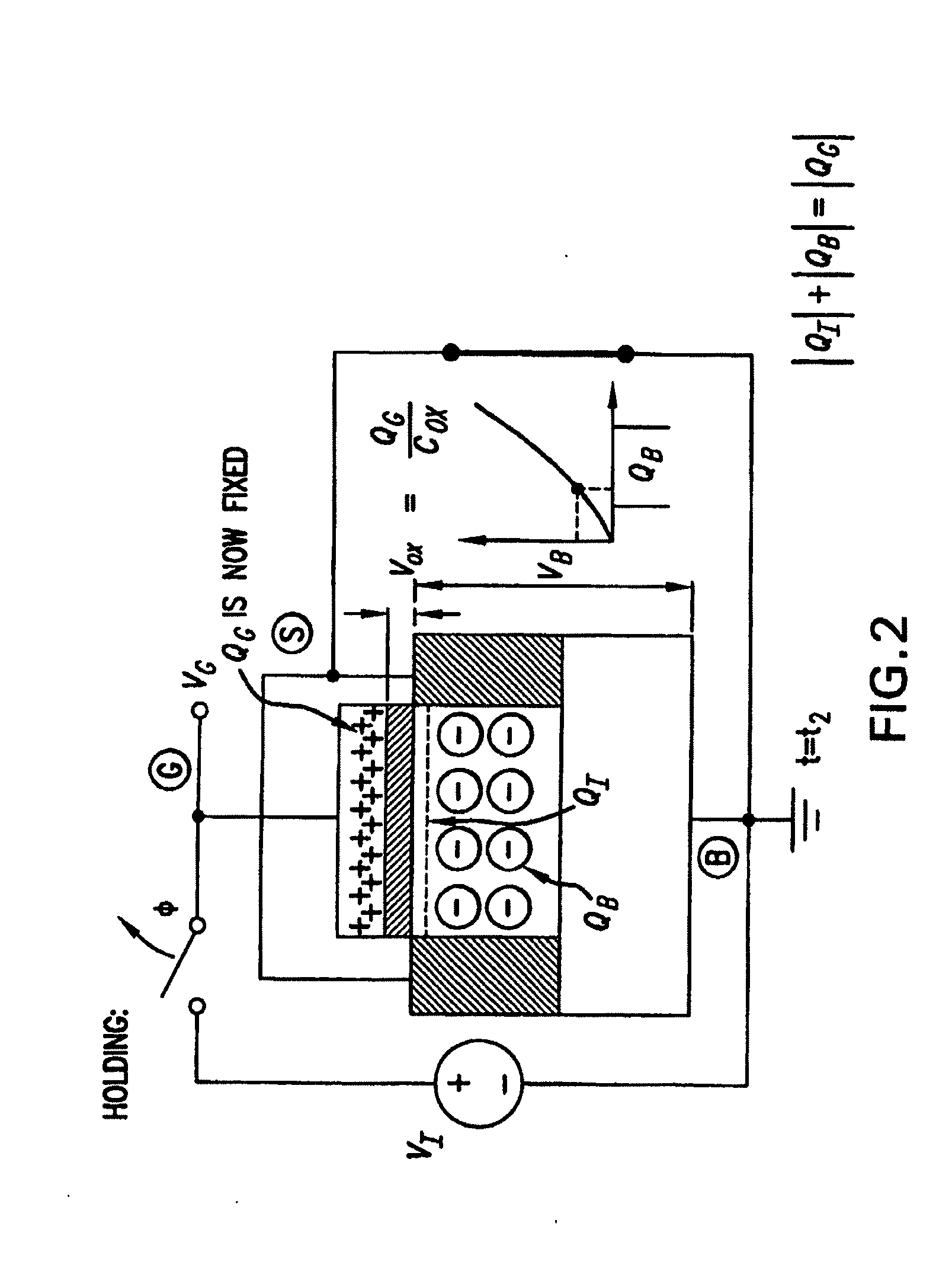
This effect is the basis of a parametric amplifier that draws little or no DC current and may be noiseless.

Method used


Image

  • MOSFET Parametric Amplifier
  • MOSFET Parametric Amplifier
  • MOSFET Parametric Amplifier

Examples


fourth embodiment

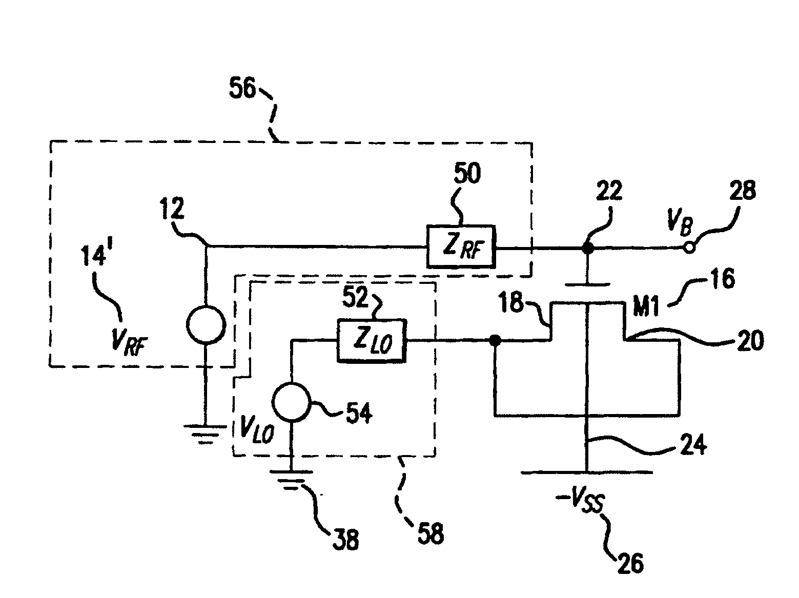
[0066]FIG. 17 depicts a fourth embodiment according to the present invention. In this embodiment, which is similar to FIG. 10, a capacitor 45′ may be connected in parallel with the gate terminal 22. Preferably a variable capacitor may be used. This may be used to control the gain by controlling the load.

[0067]In many applications like pipeline ADCs (analog-to-digital converters) a gain of 2 is required. The parametric amplifier has a maximum gain larger than 2. Variable gains may be attained by adjusting the voltage to which the source is boosted or by adjusting the capacitance 45′ that the parametric amplifier is loaded with. In a alternate embodiment, a parametric amplifier may be put in a negative feedback loop to adjust the gain to 2, by varying either or both (the pulling voltage and / or the capacitor value) of these parameters. This may require the use of other components, such as op amps and filters to obtain sufficient loop gain.

[0068]One parametric amplifier may also be used...

sixth embodiment

[0079]The requirement of a small gain for a sampled input, at a high frequency using low power is met well by the MOSFET parametric amplifier. The topology of this comparator is shown in a sixth embodiment according to the present invention in FIG. 22. In phase φ1 the input may be sampled at the gate 2230, 2240 of the MOSFET's 2210, 2220 as well as at the input of the latch. The source and drain of MOSFET's 2210, 2220 may be connected to ground 2250 at that time. In the next non-overlapping phase φ2, the source and drain of the MOSFET's 2210, 2220 may be pulled up to Vdd. This may pull in all the inversion charge from under the gate depleting the device. The results in a boosting of the gate voltage, and in differential operation in a gain.

[0080]At the end of the sampling phase, the input voltage may already be available at the gate, which is also the input of the latch. The time taken by the amplifier to amplify may be the sum of the time it takes for the drain, source terminals to...


PUM


Abstract

A circuit includes an input terminal adapted to receive an input voltage, a MOSFET having its drain terminal and its source terminal connected together, a first switching arrangement configured to be controlled by a first clock signal and adapted to selectively couple the gate terminal to the input terminal, and a further switching arrangement configured to be controlled by a further clock signal in timing relationship with the first clock signal and adapted to selectively couple the source terminal and a first voltage which is capable of pulling carriers out of a channel when the first switching arrangement is not coupling the input terminal to the gate terminal.

Description

PRIORITY AND RELATED APPLICATION[0001]This application is a continuation of International Application No. PCT / US03 / 038401, filed Dec. 2, 2003, published Jun. 17, 2004, which claims priority to U.S. provisional application 60 / 430,302, filed on Dec. 2, 2002, entitled “Applications of the Discrete-Time MOSFET Parametric Amplifier,” each of which are incorporated by reference in their entireties herein, and from which priority is claimed.FIELD OF THE INVENTION[0002]This invention relates generally to electrical circuits, and more particularly, to circuits which include MOSFET parametric amplifiers.BACKGROUND INFORMATION[0003]Issues such as noise and power consumption need to be addressed in many electrical engineering applications, such as mixer circuits, charge pump circuits, pipeline converters, and comparator circuits.[0004]For example, a sampling mixer circuit requires a quality amplifier, and designing a quality amplifier can be challenging, as circuit designers have to address iss...

Claims


Application Information

Patent Timeline
Patent Type & Authority Applications(United States)
IPC IPC(8): H03K5/00G06G7/12H01L27/08H01L27/148H01L29/78H03D7/12H03F7/00
CPCH01L27/0811H03F7/00H03D7/125H01L29/78
Inventor TSIVIDIS, YANNISRANGANATHAN, SANJEEV
Owner THE TRUSTEES OF COLUMBIA UNIV IN THE CITY OF NEW YORK
Learn More