Method and apparatus for power recycling in a display system

a technology of power recycling and display system, applied in the direction of instruments, static indicating devices, etc., can solve the problems of major problems such as emission time duration, deterioration of display image quality, and major problem of parametric capacitance inherent in display elements, and achieve the effect of efficient recycling of energy

Inactive Publication Date: 2009-10-08
SOLOMON SYSTECH
View PDF19 Cites 44 Cited by
  • Summary
  • Abstract
  • Description
  • Claims
  • Application Information

AI Technical Summary

Benefits of technology

[0020]It is a primary object of this invention to overcome the shortcoming of known existing driving method for capacitive display elements and provid

Problems solved by technology

In an electroluminescence display, parasitic capacitance inherent in the display elements represents a major problem.
Because of large capacitive loading on the lines as well as the effect of charge storage, the quality of a displayed image deteriorates when light emission time duration for any particular element becomes non-uniform in the repeated frame cycles as a result of different image patterns.
A phenomenon of off elements being induced to emit slightly due to signal cross-coupling under large-capacitance load switching conditions also degrades the display quality.
If the stored energy is simply discharged to system ground level, the discharging process wastes a substantial amount of energy.
However, the above method is ineffective for some

Method used


Image

  • Method and apparatus for power recycling in a display system
  • Method and apparatus for power recycling in a display system
  • Method and apparatus for power recycling in a display system

Examples


Embodiment Construction

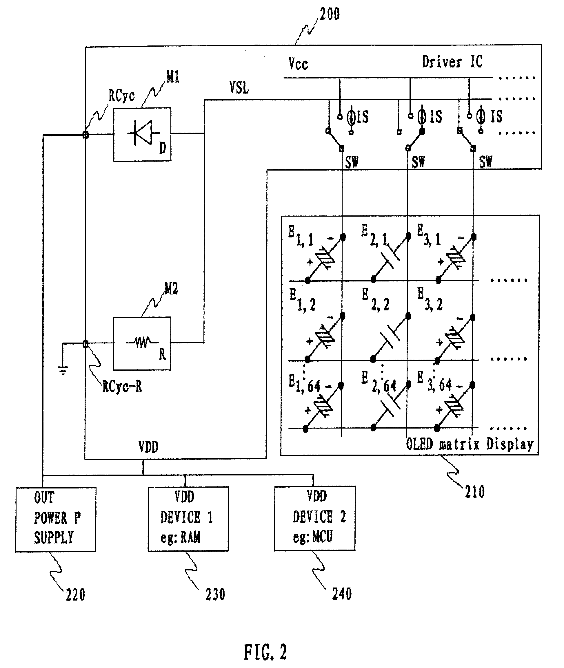
[0039]The present invention enables an effective energy recycling in various situations. The advantages of the invention include:[0040]keeping recycling efficient for any driving scheme and arbitrary display image.[0041]keeping extra circuits small for all applications. Energy flows back from the panel to power supplies and other devices like RAM, MCU directly during the discharging process. Therefore, opposite to the prior art in which extra energy storage circuits, such as a number of big volume capacitors, are required, there is no extra energy storage circuits required in this invention and resulting a small circuit area.[0042]controllable voltage level after discharging and rate of discharging. This makes a design of the present invention be compatible for various applications by just setting some parameters.

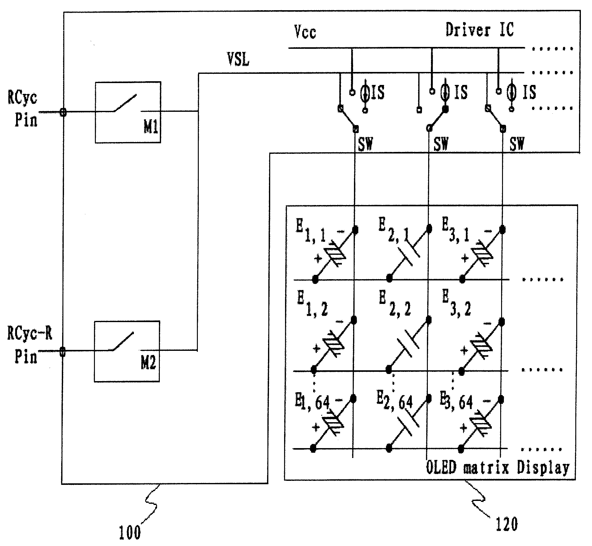
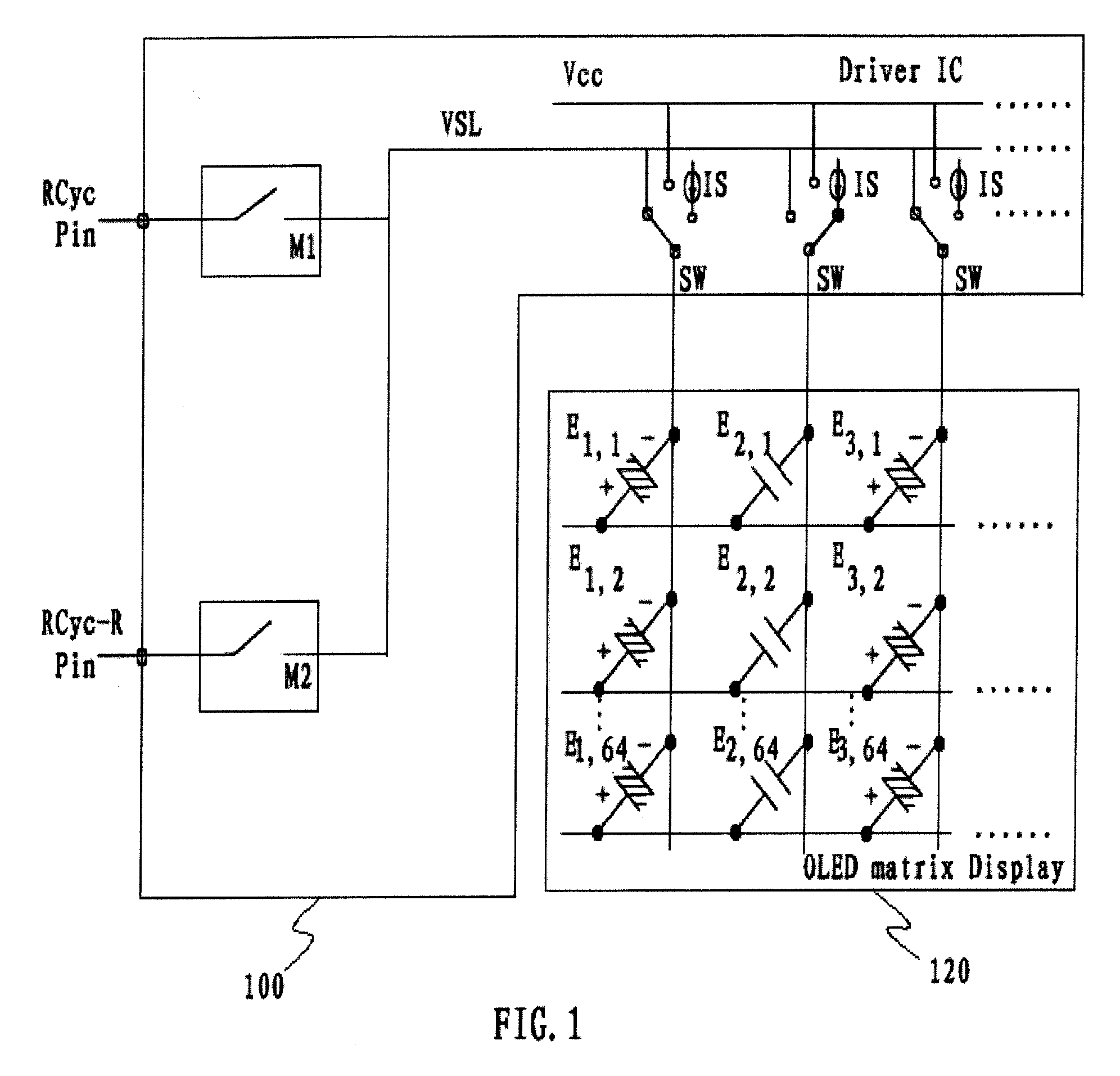
[0043]FIG. 1 shows an embodiment of the invention, for being used in a display driver IC 100, comprising a discharging module M1, a discharging module M2, a pin / pad RCyc co...


PUM


Abstract

A power recycling method and apparatus for driving capacitive display elements are described. The driving process involves charging and discharging the display elements. More particularly, the method effectively reuses some of the energy during the discharging process. Energy in display elements flows back from the panel to a power supply and other optionally to devices like RAM, MCU directly during the discharging process. Diodes between one or more power supplies and the display elements ensure that the discharge paths are disconnected when the voltage of display elements drops below the voltage of the power supply. A resistor path from the display elements to ground or a power supply lower than the display threshold voltage of the display elements guarantees that elements are turned OFF after the discharge process.

Description

TECHNICAL FIELD[0001]The present invention relates to a power recycling method and apparatus for driving a display. The driving process involves charging and discharging the display elements. More particularly, the invention is directed to effectively reuse some of the energy during the discharging process.BACKGROUND[0002]A typical electroluminescence (EL) display is an apparatus based on a panel of electroluminescence elements organized in a two-dimensional matrix of rows and columns. In general, each of the electroluminescence elements of the display has two electrodes of opposite electrical polarity: an anode and a cathode. One of the electrodes is connected to a row line while the other to a column line of the driving circuitry of the system. Each of the electroluminescence elements in the matrix is located where the addressing row and column lines for that particular element intersect.[0003]An electroluminescence element emits light when the element conducts electric current an...

Claims


Application Information

Patent Timeline
IPC IPC(8): G09G3/30
CPCG09G3/3216G09G2320/0209G09G2330/023G09G2330/021G09G2320/0233
Inventor NG, RICKY CHUNG YEEWONG, FELIX WAI YULEE, KENNETH CHI WAILAI, STEPHEN WAI-YANLO, JOHNKID
Owner SOLOMON SYSTECH
Why Eureka
Try Eureka