Monitoring of optical transmission systems based on cross-correlation operation

a technology of optical transmission system and cross-correlation operation, which is applied in the direction of transmission monitoring, transmission monitoring/testing/fault-measurement system, transmission monitoring, etc., can solve the problems of limited dynamic range, severe distortion of transmitted and back-reflected signals, and waveforms that become gaussian-noise-lik

Active Publication Date: 2009-10-15
KOREA ADVANCED INST OF SCI & TECH
View PDF4 Cites 57 Cited by
  • Summary
  • Abstract
  • Description
  • Claims
  • Application Information

AI Technical Summary

Benefits of technology

[0008]Therefore, the present invention has been made in view of the above problems, and it is an objective of the present invention to provide the in-service monitoring of the distribution of the reflectivity in a more practical manner. Unlike the conventional OTDR, the present invention does not need any short-pulse sources, but uses the data-modulated optical transmitter itself. The distribution of the back-reflected light is obtained by calculating the cross-correlation function between the signals obtained by low-pass-filtering of the data signal and back-reflected signal. This low-pass filtering is used to limit the signal bandwidth to that determined by the spatial resolution of the reflectometry, and it is much lower than the data rate of the transmission signal. For example, when the required spatial resolution is 10 m, the filter bandwidth, i.e., the cut-off frequency of the low-pass filter is chosen to be 4.4 MHz. Since the filter bandwidth is much narrower than the signal bandwidth, which is typically 640 Mbit / s˜2.5 Gbit / s in PON systems, the transmitted and the back-reflected signals are severely distorted after the low-pass filtering, and consequently, their waveforms becomes Gaussian-noise-like. However, by calculating the cross-correlation function of the filtered signals, the distribution of the reflectivity can be obtained with the designated resolution. In the present invention, the data acquisition rate can be reduced to the Nyquist frequency of the low-pass filtered signals. As a result, the requirements for the size of the memory and the data processing speed are greatly relaxed, compared with the method disclosed in U.S. Pat. No. 4,911,515. For example, for the reflectometry of the 40-km long optical transmission system, the present invention needs only 3520 samples at the sampling rate of 8.8 Msamples / s. The improvement factor is more than 300 compared with the method disclosed in U.S. Pat. No. 4,911,515. In addition, owing to the signal processing based on the cross-correlation function, the proposed method does not require the variable delay.
[0010]The present invention can utilize the existing optical transmitters without any modifications. In addition, the in-service monitoring is realized not at the supervisory wavelength but at the signal wavelength. Thus, the problem of using the conventional OTDR can be also solved.

Problems solved by technology

Since the filter bandwidth is much narrower than the signal bandwidth, which is typically 640 Mbit / s˜2.5 Gbit / s in PON systems, the transmitted and the back-reflected signals are severely distorted after the low-pass filtering, and consequently, their waveforms becomes Gaussian-noise-like.
The use of the optical transmission signal as the probe light may cause the problems of the limitation of the dynamic range.

Method used


Image

  • Monitoring of optical transmission systems based on cross-correlation operation
  • Monitoring of optical transmission systems based on cross-correlation operation
  • Monitoring of optical transmission systems based on cross-correlation operation

Examples


first example

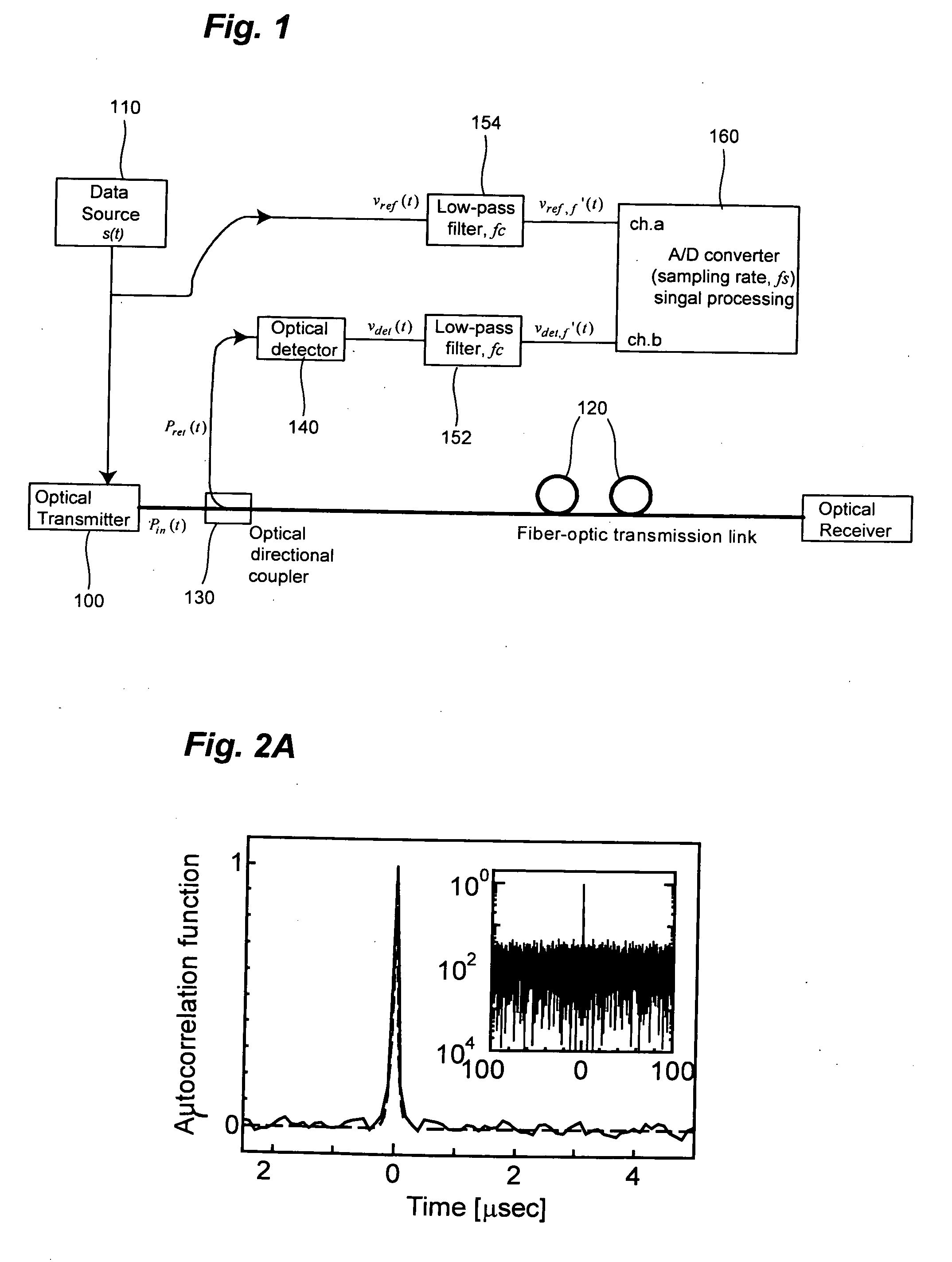
[0036]FIG. 4 shows the experimental setup 290, in which the present invention is applied to fiber-optic transmission links in service. A distributed-feedback (DFB) laser diode 200 operating at 1550.6 nm was used as an optical transmitter and is directly modulated with 1.25-Gb / s non-return-to-zero (NRZ) data using a pulse pattern generator 210 in order to demonstrate the system in service. The signal light was launched into a fiber 220 through an optical circulator 230. The average input power launched into the fiber was 0.8 dBm. To detect the back-reflected light, a conventional avalanche photo diode (APD) 240 was used, which was designed for a 155 Mb / s synchronous digital hierarchy (SDH) receiver. The data and the detected electric signals were respectively filtered out by 3-MHz LPFs 254 and 252, and digitized by a 9-bit A / D converter 260 at a sampling rate of 10 Msamples / s. Then, their cross-correlation was calculated by using a personal computer 270. In this experiment, the spati...

second example

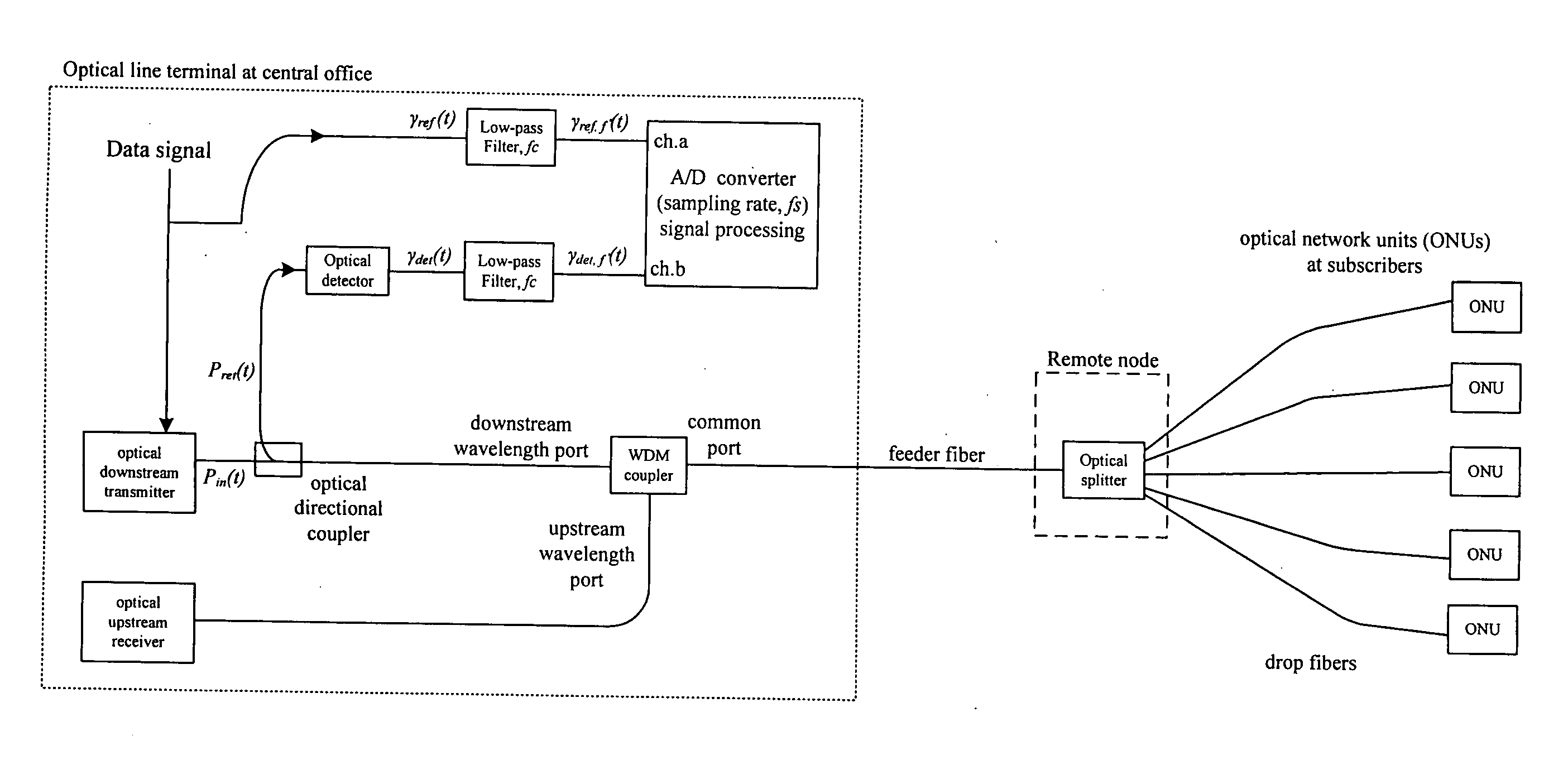
[0039]FIG. 6 shows the experimental setup used to demonstrate the in-service monitoring of the present invention in a WDM PON system. The system under test consisted of the central office 600 which includes Optical Line Terminals (OLTs) 285 and an AWG#1610, 10.0-km long feeder fiber 620, the remote node that consists of an AWG#2630, and drop fibers 640. Optical network unit (ONU) 650 was attached to the end of each drop fiber 640. The insertion loss of each AWG was about 4.1 dB and the fibers had a propagation loss of 0.21 dB / km. The AWGs were 8-ch 200-GHz spacing arrayed-waveguide gratings. Each OLT 285 used in this example was the same as the experimental setup of the first example except for the fiber 220.

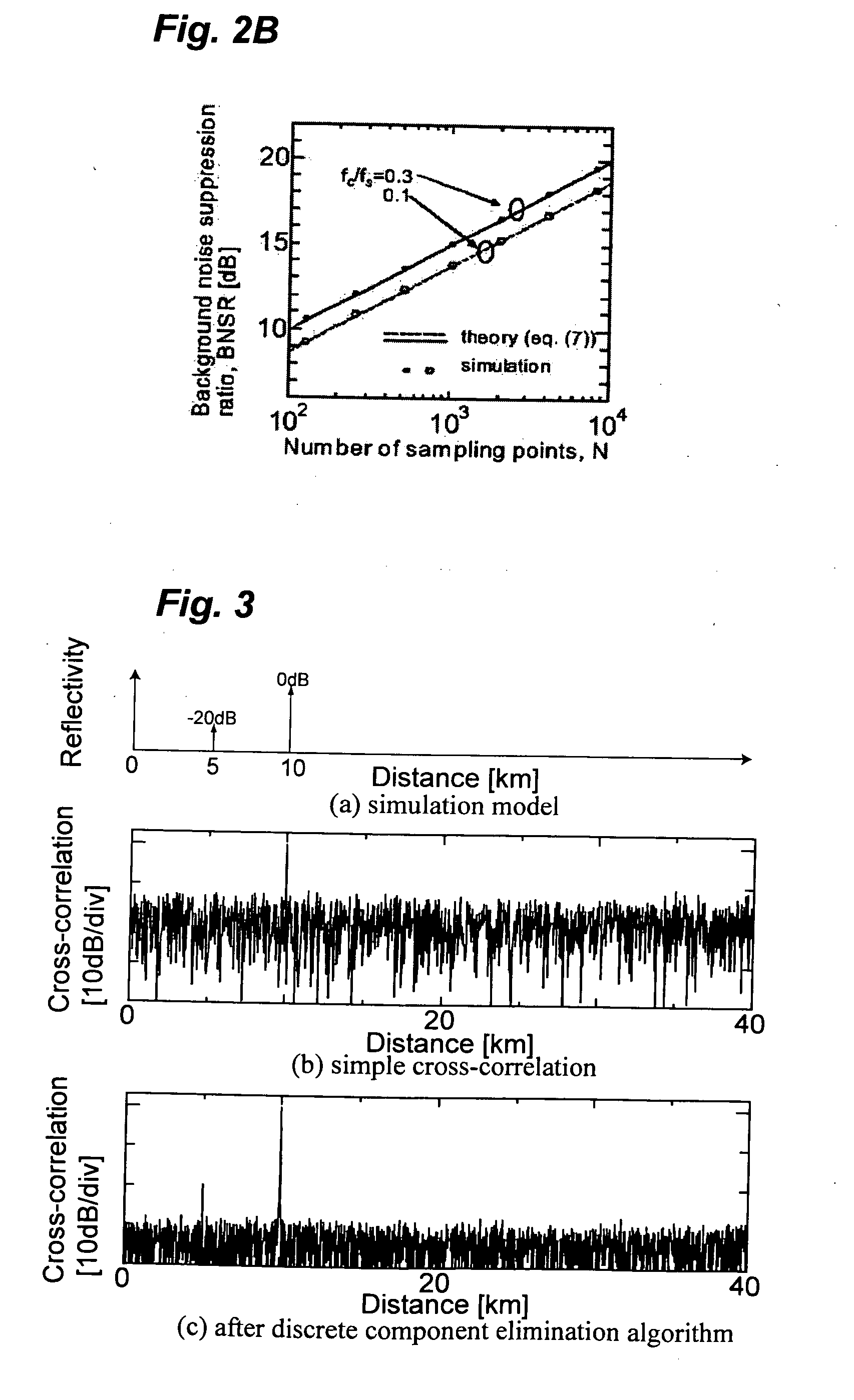
[0040]FIG. 7 shows the results of the measurement obtained in the second example, more particularly, (a) of FIG. 7 shows the cross-correlation trace measured without averaging. The discrete reflections at the central office 600 (especially at AWG#1610), the remote node (AWG#2630...

third example

[0041]FIG. 8 shows the implementation of the present invention to a PON system. The downstream signal from the optical line terminal (OLT) is distributed to the subscribers through the optical splitter at the remote node. Therefore, by applying the present invention to the PON system, the simultaneous monitoring of drop fiber cables is possible.


PUM


Abstract

In optical communication systems, an optical signal which is modulated with a data signal is transmitted from an optical transmitter, and is launched into a fiber-optic transmission link. The present invention provides a method and an apparatus for the measurement of the distribution of the reflectivity along an optical transmission line implemented by using the signal processing based on the cross-correlation function between the data signal with which the optical transmitter is modulated and the back-reflected signal returned to the optical transmitter to provide the in-service monitoring of the fiber-optic transmission link.

Description

BACKGROUND OF THE INVENTION[0001]1. Field of the Invention[0002]The present invention generally relates to optical fiber communication systems, and more particularly to a method and an apparatus for the measurement of the distribution of the reflectivity along an optical transmission line to provide the in-service monitoring of a fiber-optic transmission link.[0003]2. Description of the Related Art[0004]The distribution of the back-reflected light along the fiber-optic transmission link is an important parameter for identifying the problems in the outside plant. An optical time-domain reflectometer (OTDR) has been widely used to measure this distribution. In the measurement based on the OTDR, an optical short pulse or OTDR pulse is launched into the fiber-optic transmission link, and the reflected signal is measured as a function of the time like a lidar system. A modern OTDR can provide sufficient spatial resolution and dynamic range required for the characterization of the transmi...

Claims


Application Information

Patent Timeline
Patent Type & Authority Applications(United States)
IPC IPC(8): H04B17/00H04B10/08
CPCH04B10/071
Inventor CHUNG, YUN CHURTAKUSHIMA, YUICHI
Owner KOREA ADVANCED INST OF SCI & TECH
Why Eureka
Try Eureka