Linear track scanning imaging system and method

Active Publication Date: 2009-10-22
TSINGHUA UNIV +1
View PDF1 Cites 28 Cited by
  • Summary
  • Abstract
  • Description
  • Claims
  • Application Information

AI Technical Summary

Benefits of technology

[0010]In an example embodiment of the present invention, the plurality of array sources are arranged according to a certain spatial distribution and emit beams alternately according to a certain time sequence, such that it is possible to achieve a large scanning viewing angle with a short detector length, thereby reducing the number of the detector units required by the system and shortening the total scanning distance of the examined object.
[0011]In an example embodiment of the present invention, linear track scanning is employed instead of circular track or helical track scanning, such that the object under examination substantially performs a linear movement, and hence it is not necessary to take into account the centrifugal issue in a circular or helical movement, it is possible to carry out fast imaging of the object under examination, the imaging speed of the object under examination is greatly increased, the imaging time of the object under examination is decreased, and furthermore it is possible to meet the requirement of, and even further improve upon, the customs affair rate for article inspection to a good extent, which is very useful for an inspection system requiring a relatively high customs affair rate.
[0012]Since embodiments of the present invention utilize linear track scanning instead of circular track or helical track scanning, the objec

Problems solved by technology

For inspection of civil aviation articles, for example, since the customs affair rate is required not to be more than 0.5 meters per second, it is very difficult for even the helical CT device with a large pitch to meet the requirement.
Furthermore, for a large object such as a customs container, it is very difficult to rotate the container or the ray source.
In addition, the cost of the CT device is very high.
Because of these factors, the safety inspection system that performs stereo imaging with the CT device is not widely used.
However, the perspective imaging safety inspection system cannot avoid an overlap effect of an object

Method used


Image

  • Linear track scanning imaging system and method
  • Linear track scanning imaging system and method
  • Linear track scanning imaging system and method

Examples


Embodiment Construction

[0023]The following detailed description of embodiments is intended only to illustrate the invention, and not to limit the protective scope of the invention.

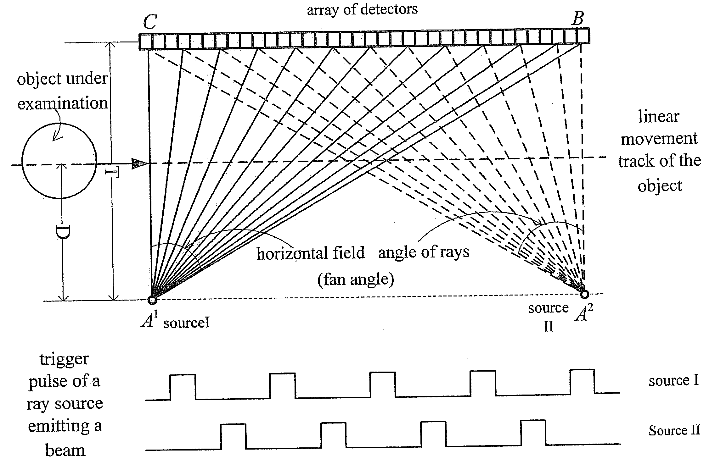
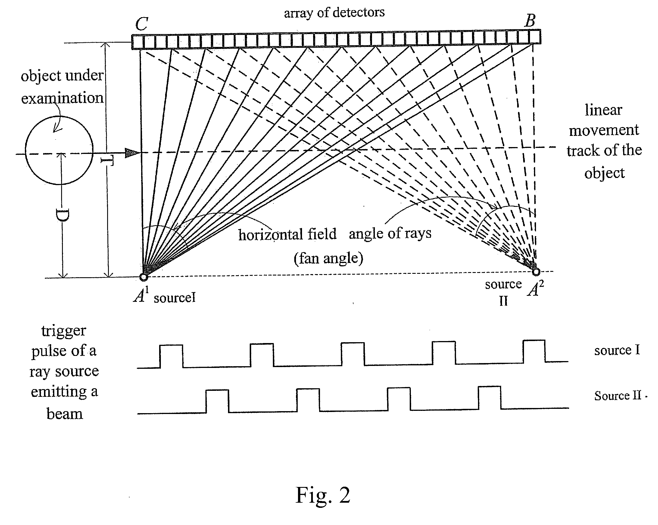
[0024]In an example embodiment of the present invention, a multi-source linear track scanning imaging system achieves stereo imaging by employing multi-source linear track scanning to obtain projection data and using CT image reconstruction and data processing techniques to obtain a tomographic image. The travel track of an object under examination is a linear track. The receiving plane of an array of detectors is arranged to be parallel to its corresponding linear track, at least two ray sources arranged on a same side as each other with respect to the array of detectors, and preferably distributed in a line parallel to the moving track of the object under examination. The individual ray sources form respectively a separate scanning viewing angle with the array of detectors, but partial overlap is allowed. In operation, a ray g...


PUM


Abstract

In a linear track scanning imaging system and method, the imaging system may include: a ray generating unit having a plurality of ray sources that emit beams alternately, only one ray source at a time; an actuating arrangement causing an object under examination to move with respect to the linear track scanning imaging system along a linear track, leading the object to pass through a scanning area of the linear track scanning imaging system; a data collecting unit that collects projection data of the object for each ray source; an imaging unit that reconstructs an image of the object under examination based on the projection data collected for each ray source; and a display unit for displaying the reconstructed image.

Description

FIELD OF THE INVENTION[0001]The present invention relates to the field of radiation imaging, and more particularly, to a linear track scanning imaging system and method thereof.BACKGROUND INFORMATION[0002]Safety inspection is of great significance in the fields of anti-terrorism, cracking down on drug trafficking and smuggling, etc. After the U.S. September 11th event, more and more attention is paid to safety inspection all over the world, and especially at public locations such as airports, stations, customs, and dock, etc., a series of safety inspection measures is taken to perform a strict inspection on passengers' baggage and articles, cargo container, etc.[0003]Currently, a predominant imaging technology employed by a widely used safety inspection system is radiation imaging technology. According to the principle of rays' exponential decay, the radiation imaging technology adopts a system in which a ray source irradiates an object under examination on one side of the object un...

Claims


Application Information

Patent Timeline
IPC IPC(8): G01N23/04
CPCG01B15/00G03B42/00G01V5/0058G01V5/005G01V5/0016
Inventor ZHANG, LILIU, YINONGCHEN, ZHIQIANGLI, YUANJINGGAO, HEWEIXING, YUXIANGZHAO, ZIRANXIAO, YONGSHUN
Owner TSINGHUA UNIV
Why Eureka
Try Eureka