Selective Deposition Modeling Using CW UV LED Curing

a technology of selective deposition modeling and led curing, which is applied in the field of solid freeform fabrication, can solve the problems of affecting the quality of cw uv led curing, and unable to effectively initiate curing in these materials

Active Publication Date: 2009-10-29
3D SYST INC
View PDF51 Cites 121 Cited by
  • Summary
  • Abstract
  • Description
  • Claims
  • Application Information

AI Technical Summary

Benefits of technology

[0013]A second aspect of the invention is a continuous-wave (CW) ultraviolet (UV) curing system for curing a UV-curable material deposited in sequential layers. The CW UV curing system comprises one or more UV LEDs that emit CW UV radiation and a power supply configured to provide power to the one or more LEDs and to control the operation of the one or more LEDs so as to provide exposures for the deposited layers.

Problems solved by technology

However, developing a flood UV exposure system that effectively initiates curing in these materials has proven problematic.
The region is so small that the free radicals lack the opportunity to react with the oxygen in the atmosphere.
However, oxygen inhibition is a significant problem in SDM applications where a broad planar flood exposure is desired to initiate the curing process.
Although this phenomena can be overcome by submersing the SDM build environment in an inert gas, providing such a system adds additional complexity and expense to an SDM apparatus.
Undesirably, the high levels of heat generated by these lamps pose significant problems in SDM.
Not only is the amount of power consumed by these lamps to maintain the emission substantial, but they also have long warm up times which necessitates that they be constantly operated.
Further, experiments with constant UV emitting lamps not only demonstrate that they consume significant amounts of power, typically around 1500 Watts, but also that many curable formulations would not cure due to oxygen inhibition.
Although these commercially available systems are capable of overcoming the problem of oxygen inhibition, they are generally not practical for use in SDM.
For example, commercially available power supplies for use in charging these pulse systems have large input power requirements, often around 40 kilowatts or more.
Thus, these flash curing systems operate at power levels that are too high to be useful in SDM apparatuses.
For SDM applications a lower power consumption flash curing system is needed, but not available.
While having many advantages, the flash curing system still relies on lamps that generate significant amounts of energy in the infrared (IR) region of the electromagnetic spectrum and also still consume relatively large amounts of power.
Also, the system requires additional complexity to create the multiple light pulses.

Method used


Image

  • Selective Deposition Modeling Using CW UV LED Curing
  • Selective Deposition Modeling Using CW UV LED Curing
  • Selective Deposition Modeling Using CW UV LED Curing

Examples


example curable

Phase Change Materials

[0044]A number of radiation-curable phase change formulations have been developed for being dispensed by a dispensing device, such as a Z850 print head available from Xerox Corporation of Wilsonville, Oreg. The components of four exemplary build material formulations are provided by weight percent in Table 1, below.

TABLE 1Mfg. IDGeneral ComponentNo.NameEx. 1Ex. 2Ex. 3Ex. 4CN980Urethane Acrylate7.2% 6.5%CN981Urethane Acrylate26%E3200Epoxy Acrylate14%6.0%CN975Hexafunctional7.2% Urethane AcrylateCN2901Urethane Acrylate27.5%  27%18.7% SR203TetrahydrofurfurylMethacrylateSR205Triethylene glycol33%46.5%  41.05% dimethacrylateSR3402-phenoxyethylmethacrylateSR313Lauryl methacrylate18%SR454Ethoxylated34.5% TrimethylolpropaneTriacrylateSR604polypropylene12.0% glycolmonomethacrylateCD406Cyclohexane30%dimethanoldiacrylateSR493DTridecyl19%MethacrylateADS038Urethane wax 7%5.3% 10%10.0% ADS043Urethane wax4.3%  6%1.5% 2.0%I-184Photo-initiator 2% 2% 2%3.75% TOTAL100% 100% 100% 1...

example sdm

Apparatus

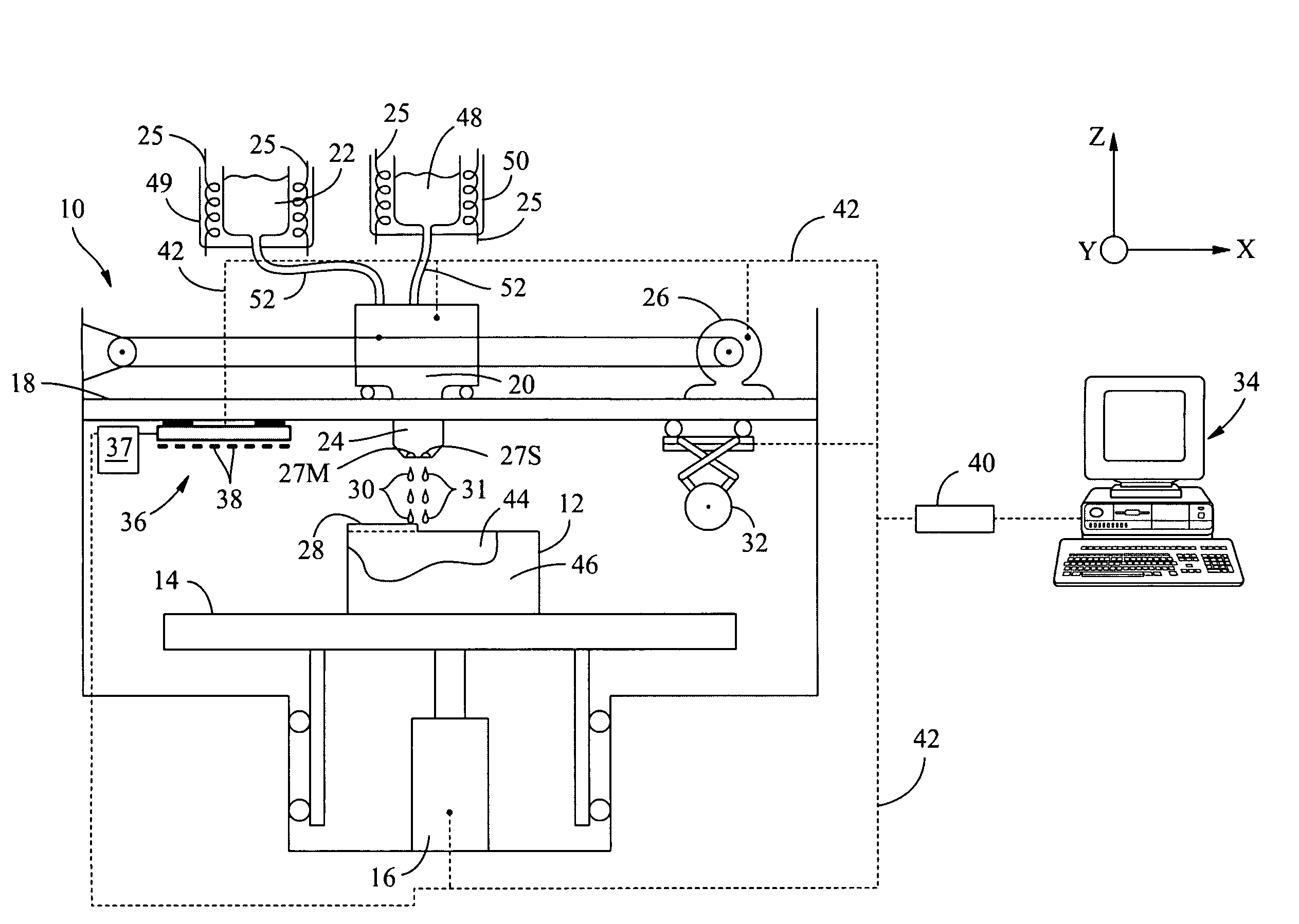
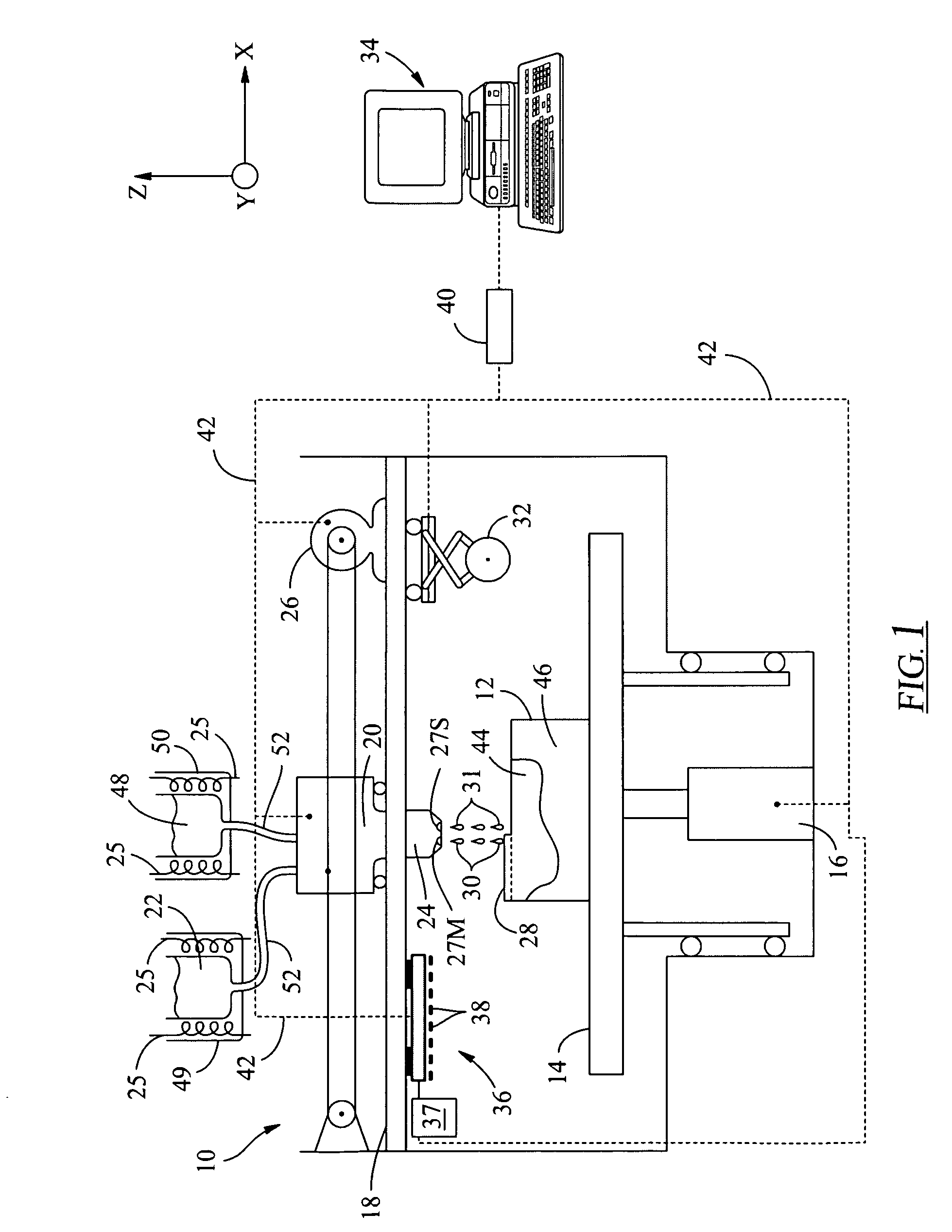
[0105]Now referring to FIG. 13, the SDM apparatus schematically shown in FIG. 3 is shown as 12. To access the build environment, a slideable door 82 is provided at the front of the apparatus. The door 82 does not allow radiation within the apparatus to escape into the environment. The apparatus is configured such that it will not operate or turn on with the door 82 open. In addition, when the apparatus is in operation, the door 82 will not open. Material feed doors 84 are provided so that the curable phase change material can be inserted into the apparatus through one door 84 and the non-curable phase change material can be inserted into the apparatus through the other into their respective feed magazines (not shown). A waste drawer 86 is provided at the bottom end of the apparatus 10 so that the expelled waste material can be removed from the apparatus. A user interface 88 is provided which is in communication with the external computer previously discussed which tracks re...


PUM

PropertyMeasurementUnit
irradianceaaaaaaaaaa
central wavelengthaaaaaaaaaa

Abstract

A continuous-wave (CW) ultraviolet (UV) curing system for solid freeform fabrication (SFF) is provided, wherein the curing system is configured to provide an exposure of UV radiation for one or more layers of UV-curable material. One or more UV exposures may initiate curing of a curable material in the layer dispensed by a solid freeform fabrication apparatus. One approach to provide the single or multiple UV exposures is the use of one or more UV LEDs, which generate UV radiation without generating any substantial amounts of infrared (IR) radiation at the same time. This allows for the curing process to be energy efficient and also allows for the SFF system to be far less complex.

Description

FIELD OF THE INVENTION[0001]The present invention relates in general to solid freeform fabrication, and in particular to methods, systems and apparatus for selective deposition modeling using continuous ultraviolet (UV) radiation to cure layers of a build material to form three-dimensional structures or objects.BACKGROUND OF THE INVENTION[0002]Several technologies are used for rapidly creating solid, three-dimensional models, prototypes, and parts for limited-run manufacturing. These technologies are generally called Solid Freeform Fabrication (SFF) techniques and include stereolithography, selective deposition modeling (SDM), three-dimensional printing, laminated object manufacturing, selective phase area deposition, multi-phase jet solidification, ballistic particle manufacturing, fused deposition modeling, particle deposition, laser sintering, and the like. Generally in SFF techniques, complex parts are produced from a modeling material in an additive fashion, as opposed to conve...

Claims


Application Information

Patent Timeline
Patent Type & Authority Applications(United States)
IPC IPC(8): B29C35/08
CPCB29C67/0059B29C67/0077B29C67/0088B29C67/0066B29C2035/0827B29C64/112B29C64/135B29C64/153B29C64/393
Inventor LIM, JIN HONGANGULO, HERNANDO VINCENTECLAY, JOHN D.MOUSSA, KHALIL
Owner 3D SYST INC
Why Eureka
Try Eureka