
Plating apparatus with direct electrolyte distribution system

a technology of direct electrolyte distribution and plating apparatus, which is applied in the direction of electrolysis components, manufacturing tools, electrolysis processes, etc., can solve the problems of limiting process capability, limiting process capability, and not providing an even plating thickness, so as to improve thickness equity and less plating

Active Publication Date: 2009-11-05
ALCATEL LUCENT SAS
View PDF5 Cites 11 Cited by
  • Summary
  • Abstract
  • Description
  • Claims
  • Application Information

AI Technical Summary

Benefits of technology

[0013]Some current approaches use shading of parts or special anodes. Unfortunately, this limits process capability and narrows process control. These flaws are believed to make the plating process very unstable. Accordingly, various exemplary embodiments, prevent plating thickness of an uncontrolled variability. Likewise, various exemplary embodiments improve plating process and plated parts quality control.
[0021]In many current embodiments, the most plated metals electrolytic deposit stays on surface(s) that are closer to opposite electrodes. Accordingly, it is believed that areas more desirable to be plated get two to three times less deposit than desired. It is believed that this creates a need to extend timing and electrode distances for plating parts with complicated surfaces. This in turn leads to over-plating at some areas, more voltage between electrodes, and narrowing the window for process parameters control.
[0022]This is also believed cause the thickness of the part in different areas and the cost of the process to become uncontrollable. Most plating gets on top of the part. This is undesirable, and might result in closing open mounting holes, creating unwanted build-ups, and creating excessive roughness at some areas. The foregoing all results in lowering a usability of the part being plated.
[0023]The walls and build-in parts shade the area of importance for parts used in radio frequency applications. This affects electrolyte circulation inside the part, making external ion delivery to the plated surface the slowest stage of the process and the major process control stage. As a result the bottom of the part that is located further from the anode than the top of the part will have less plating than desired to achieve performance specifications for the part. Improving electrolyte circulation in the area of interest, as close to the surface of the part as possible, will improve thickness equity on all surfaces while maintaining minimally desired thicknesses on specified areas.

Problems solved by technology

It is believed that current solutions do not provide an even plating thickness, or control the thickness effectively where plating is needed.
Unfortunately, the bottom of the housing is believed to be pertinent to good plating.
Unfortunately, this limits process capability and narrows process control.
These flaws are believed to make the plating process very unstable.

Method used


Image

  • Plating apparatus with direct electrolyte distribution system
  • Plating apparatus with direct electrolyte distribution system
  • Plating apparatus with direct electrolyte distribution system

Examples


Embodiment Construction

[0032]Referring now to the drawings, in which like numerals refer to like components or steps, there are disclosed broad aspects of various exemplary embodiments.

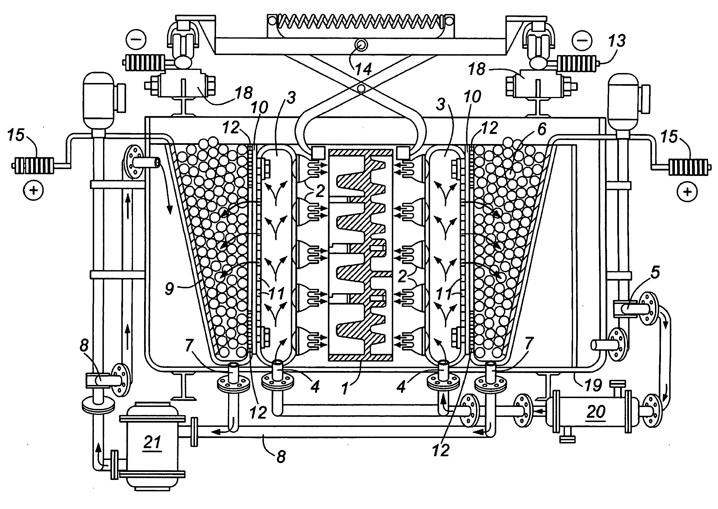
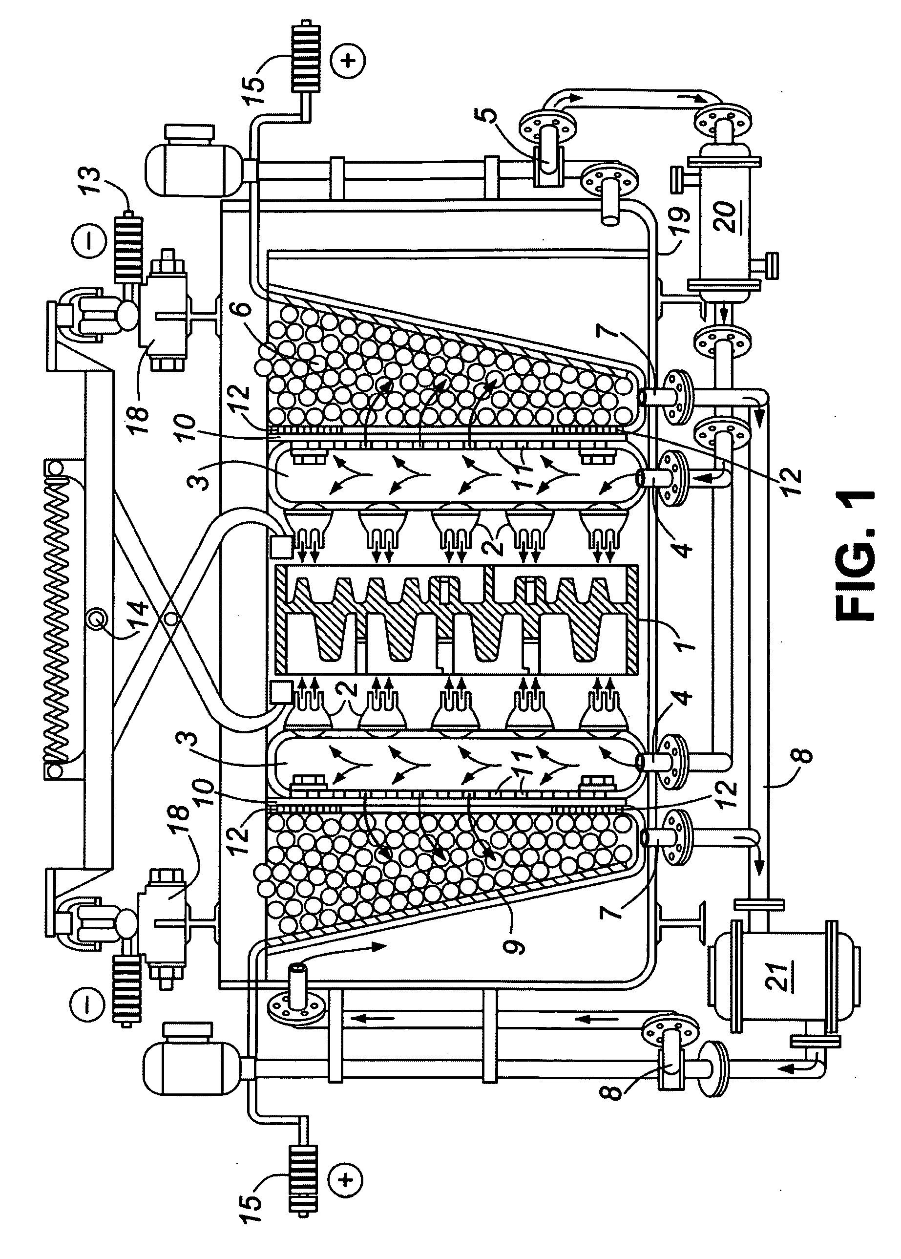
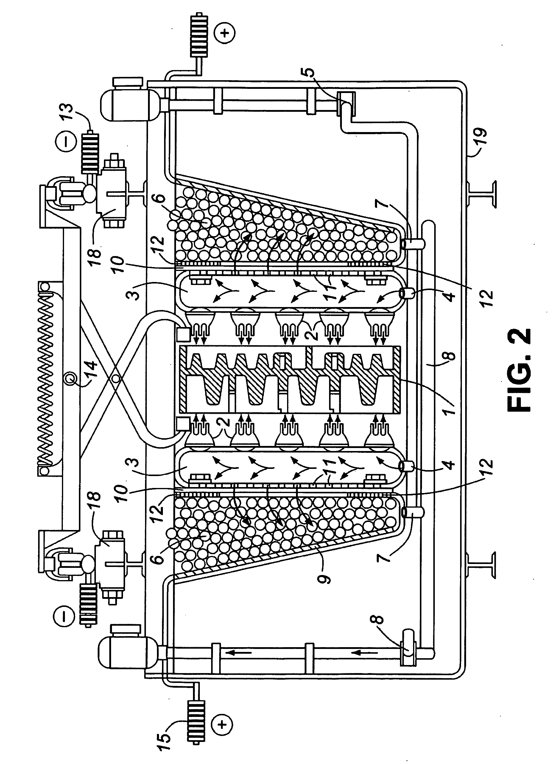
[0033]FIG. 1 is a partially schematic, partially cross-sectional view of a first exemplary embodiment of a plating apparatus with direct electrolyte distribution system.

[0034]The plated part (1), or two parts combined and racked together, is placed in the center of the plating bath next to or between positively charged electrodes, anodes (6). The apparatus is filled with electrolyte. The level of the electrolyte is controlled by the height of a leveled wall or by any other method.

[0035]In various exemplary embodiments, overflow of electrolyte, if needed for electrolyte flow control, is collected in a special compartment (16) and pumped back by pump (5) into specially designed collector-distributor (3). This is shown in FIG. 3 and FIG. 4. In the embodiments of FIG. 1 and FIG. 2, the system is all connected such that it does ...


PUM

PropertyMeasurementUnit
Flow rateaaaaaaaaaa
Electrical conductoraaaaaaaaaa

Abstract

A plating apparatus with direct electrolyte distribution system, including one or more of the following: an electrolyte tank; an electrolyte distribution compartment within the electrolyte tank, the electrolyte distribution compartment for containing electrolyte, the electrolyte distribution compartment having a first side and a second side; a pump having a fluid connection to the electrolyte distribution compartment for applying pressure to the electrolyte; a plurality of nozzles connected to the first side of the electrolyte distribution compartment, the electrolyte being forced through the plurality of the nozzles from the electrolyte distribution compartment to a part to be plated when the pump applies pressure to the electrolyte in the electrolyte distribution compartment; an electrolyte collection compartment within the electrolyte tank, the electrolyte collection compartment being in fluid communication with the electrolyte distribution compartment; and a removable screen between the electrolyte collection compartment and the second side of the electrolyte distribution compartment.

Description

BACKGROUND OF THE INVENTION[0001]1. Field of the Invention[0002]This invention relates generally to coating or plating a surface of an object with an electrolyte.[0003]2. Description of Related Art[0004]Coating or plating a surface of a substance with an electrolyte, or electroplating, has evolved. There are an ever-increasing number and widening types of applications of this branch of practical science and engineering. Some of the technological areas in which this is applied include macro-electronics, microelectronics, optics, optical-electronics, and sensors of most types. There are many other technological areas where electroplating is used.[0005]Some industries use electroplating instead of other options. For example, the automobile industry uses chrome plating instead of evaporation, sputtering, chemical vapor deposition (CVD) and the like, to enhance the corrosion resistance of metal parts. Reasons for using electroplating include both economy and convenience.[0006]By way of i...

Claims


Application Information

Patent Timeline
IPC IPC(8): C25D17/00
CPCC25D5/08C25D17/08C25D21/06C25D21/02C25D17/008
Inventor LUKKARILA, TEPPO M.YESILEVICH, SERGEY Y.
Owner ALCATEL LUCENT SAS
Learn More