Exreme ultraviolet light source apparatus

a light source and ultraviolet light technology, applied in the field of extreme ultraviolet (euv) light source devices, can solve the problems of easy deformation of the reflectance long use of the euv collector mirror, etc., and achieve the effect of high transmittance, easy deformation, and high transmittan

Active Publication Date: 2009-11-05
GIGAPHOTON
View PDF2 Cites 70 Cited by
  • Summary
  • Abstract
  • Description
  • Claims
  • Application Information

AI Technical Summary

Benefits of technology

[0013]According to the one aspect of the present invention, by shielding the structural member in the vacuum chamber with the shielding member including the material having a high transmittance for the EUV light, even if the fast ions generated from the plasma collide with the shielding member, particles of the material having the high transmittance for the EUV light are emitted out

Problems solved by technology

Therefore, the reflectance of the EUV collector mirror is not easil

Method used


Image

  • Exreme ultraviolet light source apparatus
  • Exreme ultraviolet light source apparatus
  • Exreme ultraviolet light source apparatus

Examples


first embodiment

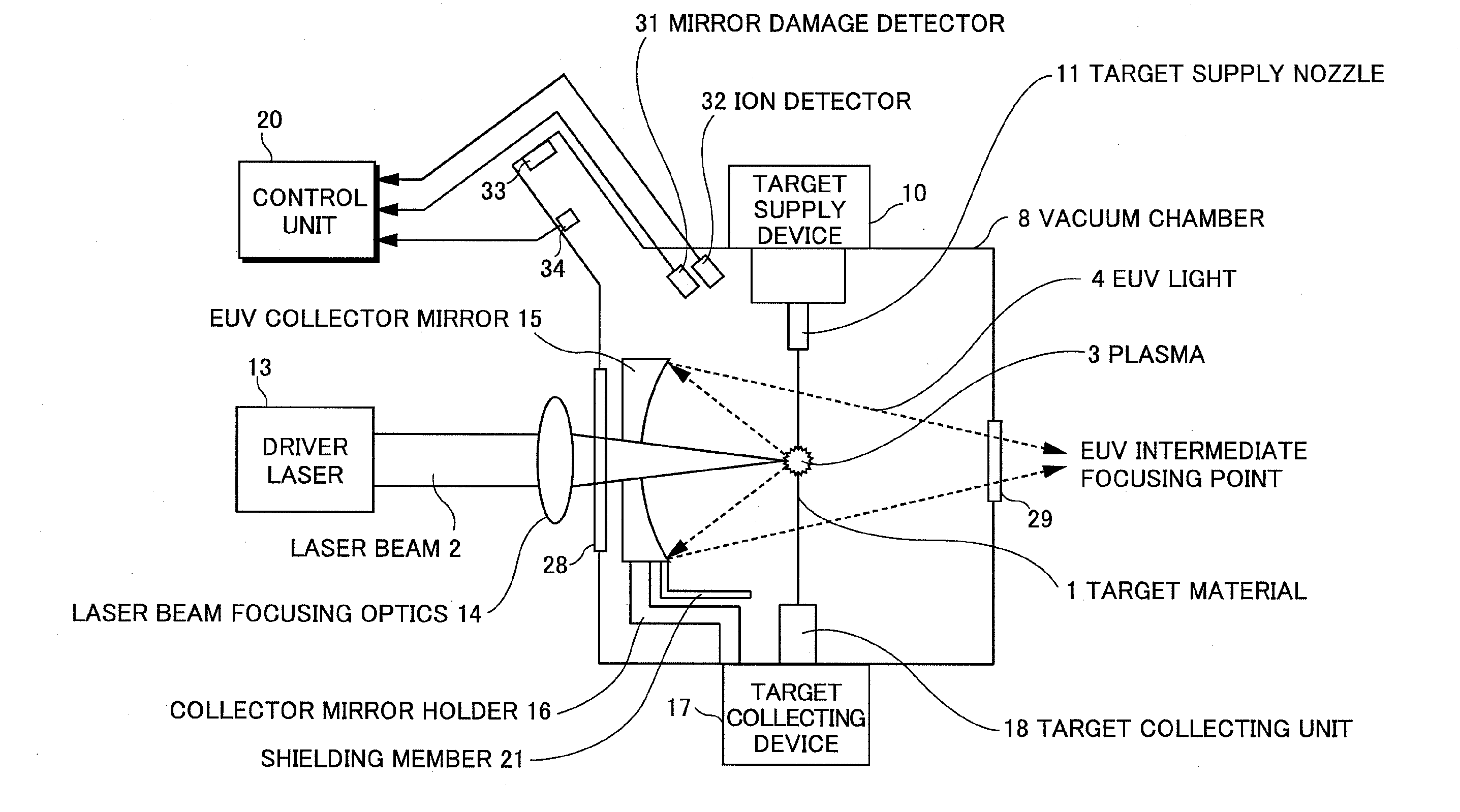
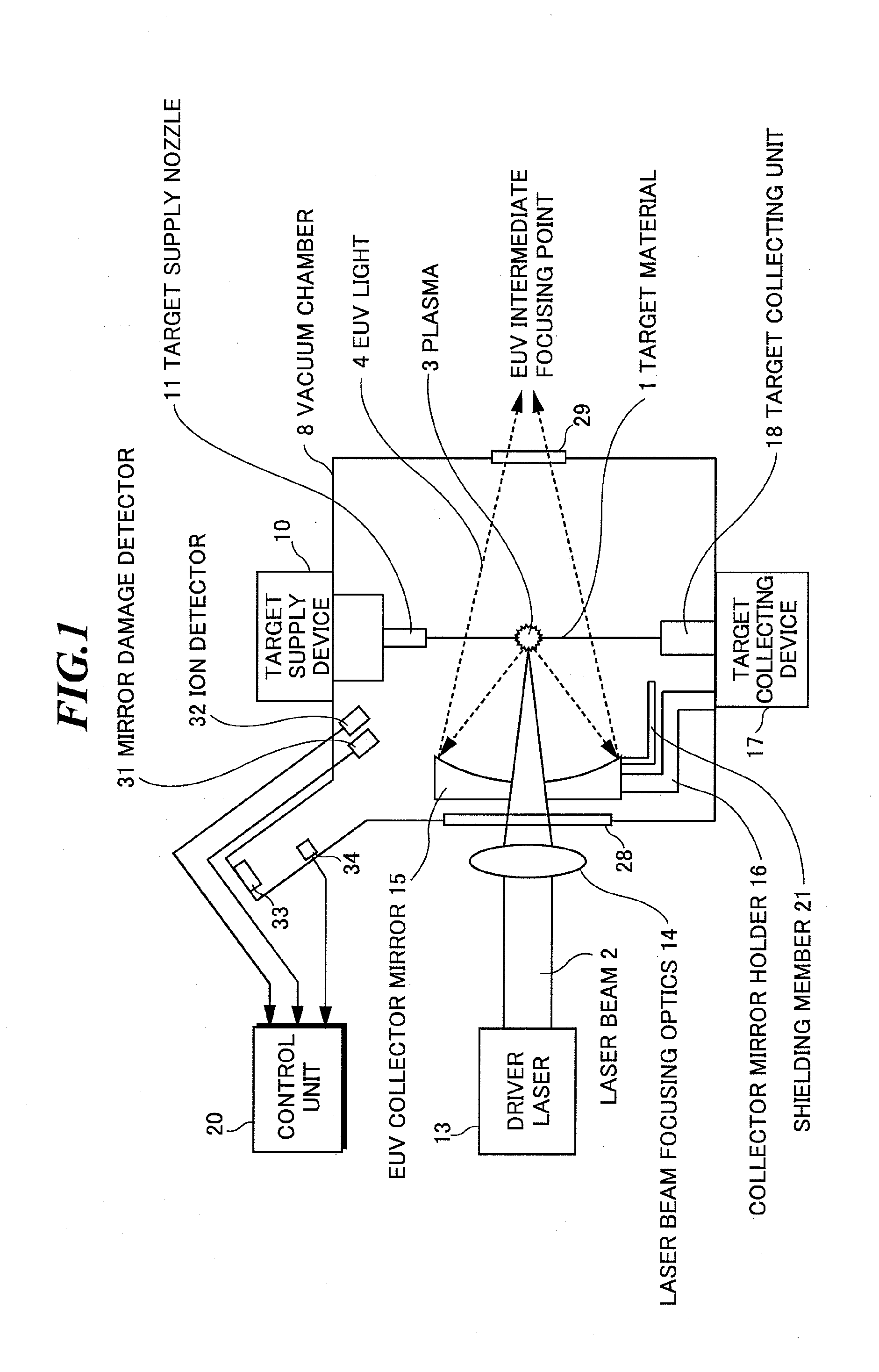
[0045]FIG. 1 is a conceptual side view illustrating an EUV light source apparatus according to the present invention. The EUV light source apparatus according to the embodiment adopts a laser produced plasma (LPP) system of generating EUV light by applying a laser beam to a target material to be excited.

[0046]As illustrated in FIG. 1, the EUV light source apparatus includes: a vacuum chamber 8 in which the EUV light is generated; a target supply device 10 for supplying a target material 1; a driver laser 13 for generating an excitation laser beam 2 to be applied to the target material 1; laser beam focusing optics 14 for focusing the excitation laser beam 2 generated by the driver laser 13; an EUV collector mirror 15 for collecting and outputting the EUV light 4 emitted from plasma 3 generated by applying the excitation laser beam 2 to the target material 1; a collector mirror holder 16 for supporting the EUV collector mirror 15 in the vacuum chamber 8; a target collecting device 17...

second embodiment

[0065]Next, the present invention will be described.

[0066]FIG. 5 is a schematic diagram illustrating an internal structure of an EUV light source apparatus according to the second embodiment of the present invention that covers the structural member by employing a plates made of the material having a high transmittance for the EUV light as the shielding member. FIG. 6 is a schematic diagram illustrating a modification of the EUV light source apparatus according to the second embodiment of the present invention.

[0067]The EUV light source apparatus according to the present embodiment is provided with shield plates 22 made of the material having a high transmittance for the EUV light in order to cover the collector mirror holder 16 and structural member 100 which are exposed to the plasma in the vacuum chamber as illustrated in FIG. 5. In the present embodiment, as the material of the shield plate 22, the silicon (Si) having a high transmittance for the EUV light is used. However, zirc...

third embodiment

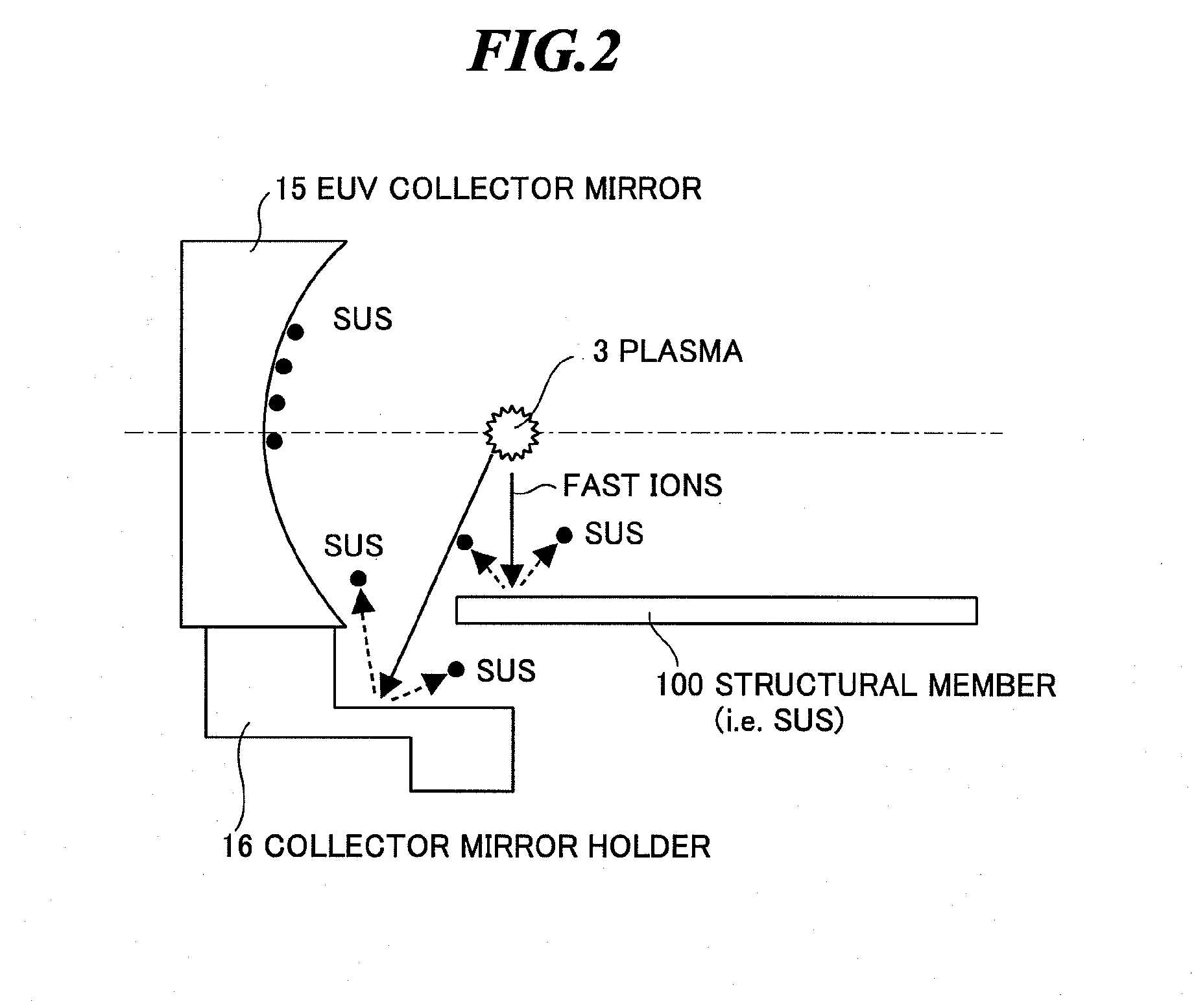
[0070]However, the collector mirror holder 16 and the structural member 100 arranged in the vacuum chamber are made of stainless steel in many cases, and the structural member itself has a complicated shape in many cases. On the other hand, silicon (Si) has the feature that it breaks easily, processing such as bending is impossible, and it is inferior in workability. Therefore, it may be difficult for silicon (Si) to cover the structural member having complicated shapes by processing the silicon as a plate. Then, a third embodiment described in the following is an embodiment noticing workability of the material.

[0071]FIG. 7 is a schematic diagram illustrating an internal structure of an EUV light source apparatus according to the third embodiment of the present invention that provides a shielding member by coating the structural member with coating material having a high transmittance for the EUV light. In the third embodiment, a coating material 23 is formed by coating at least a p...


PUM


Abstract

An extreme ultraviolet light source apparatus in which only particles having a high transmittance for EUV light adhere to an EUV collector mirror even if fast ions emitted from plasma collide with a structural member in a vacuum chamber, and thereby, the reflectance thereof is not easily degraded. The apparatus includes: a vacuum chamber; a target supply unit for supplying a target to a predetermined position in the vacuum chamber; a driver laser for applying a laser beam to the target to generate the plasma; a collector mirror for collecting and outputting extreme ultraviolet light emitted from the plasma; a collector mirror holder for supporting the collector mirror; and a shielding member formed of a material having a high transmittance for the extreme ultraviolet light, for shielding the structural member such as the collector mirror holder from the ions generated from the plasma.

Description

BACKGROUND OF THE INVENTION[0001]1. Field of the Invention[0002]The present invention relates to an extreme ultraviolet (EUV) light source apparatus to be used as a light source of exposure equipment.[0003]2. Description of a Related Art[0004]Recent years, as semiconductor processes become finer, photolithography has been making rapid progress to finer fabrication. In the next generation, micro-fabrication at 60 nm through 45 nm, further, micro-fabrication at 32 nm and beyond will be required. Accordingly, in order to fulfill the requirement for micro-fabrication at 32 nm and beyond, for example, exposure equipment is expected to be developed by combining an extreme ultraviolet (EUV) light source generating EUV light having a wavelength of about 13 nm and a reduced projection reflective system.[0005]As the EUV light source, there are three kinds of light sources, which include an LPP (laser produced plasma) light source using plasma generated by applying a laser beam to a target, a ...

Claims


Application Information

Patent Timeline
IPC IPC(8): H05G2/00
CPCG03F7/70033G03F7/70808G03F7/70916G03F7/70941H05G2/005H05G2/003H05G2/008H05G2/006G03F7/7095
Inventor ABE, TAMOTSUSOMEYA, HIROSHISUGANUMA, TAKASHIYABU, TAKAYUKI
Owner GIGAPHOTON
Why Eureka
Try Eureka