Mass/Volume Estimation of Contamination, Removal and/or in situ Treatment Using Subsurface Pressure Waves

a technology of subsurface pressure and mass/volume estimation, which is applied in the direction of surveying, contaminated groundwater/leachate treatment, and well accessories, etc., can solve the problems of difficult and inability to completely remove non-aqueous phase liquids such as napl, and achieve the effect of enhancing degradation and/or transformation of at least a portion

Active Publication Date: 2009-11-12
REMMETRIK
View PDF12 Cites 8 Cited by
  • Summary
  • Abstract
  • Description
  • Claims
  • Application Information

AI Technical Summary

Benefits of technology

[0031](d) simultaneously or subsequently introducing nutrients, chemical oxidants, or other treatment agents into the injection well wherein the treatment agents are caused to flow from the lower perforated portion of the injection well into the pores, voids, or apertures in the saturated zone and capillary fringe zone to effect the enhanced degradation and / or transformation of at least a portion of the contaminants present.

Problems solved by technology

The remediation of soil and groundwater contaminated by light (lighter than water) non-aqueous phase liquids (LNAPL) and dense (heavier than water) non-aqueous phase liquids (DNAPL), collectively known as non-aqueous phase liquids (NAPL), remains a difficult problem where these contaminants exist as a residual (undissolved) or free product within a soil and / or rock matrix.
LNAPLs (e.g., oily substances that float in water) and DNAPLs (e.g., chlorinated solvents, coal tar, creosote, that sink in water) are not readily removable in their entirety and continue to contaminate groundwater and soil and prevent or restrict use of the site in which these contaminants exist, or pose a threat of migration onto nearby properties.
In the case of LNAPL, free product can adversely impact soil and groundwater and migrate onto other properties.
One of the difficulties in remediation of LNAPLs and DNAPLs is that the mass or volume of contaminant is poorly understood or completely unknown.
In the case of LNAPLs, invalid methods are most often employed to estimate the volume of contaminant, so the recoverable quantity of contaminant is overestimated or underestimated and the benchmarks for cleanup are uncertain or unknown; largely they are unattainable and unrealistic using conventional products and methods.
The non-recoverable LNAPL, that portion sequestered within the soil or rock matrix, i.e. the residual, remains behind in pore spaces or voids and continues to adversely affect soils and groundwater.
The residual is vastly more difficult to remove than the free product using conventional in situ methods and, in practice, removal is effectively infeasible.
Removal of subsurface DNAPL is very difficult because these compounds dispense, forming fingers and pools making them very hard to locate and accurately quantify.
Most of the DNAPL exists as a residual that occupies the pore spaces or voids and is exceedingly difficult to remove, treat, or otherwise access, depending on the site geological characteristics.
Depending on the size of the pores, voids, or apertures, the LNAPL or DNAPL is more strongly or weakly held; smaller openings hold contaminants more strongly No known conventional technology can effectively remove contaminants from the pores or voids while the geologic media remains in place (in situ).
The process, however, suffers from the need to have a reliable benchmark as to the mass or volume of contaminant present so as to know how much treatment chemical is required and for how long treatment will take, and a reliable benchmark as to when the contaminant has been effectively neutralized or destroyed.
Another important limitation of this approach is that the greatest contaminant concentrations do not necessarily coincide with the location of the greatest amount of contaminant mass or volume.
Without a reliable before and after estimation of volume or mass, effective treatment is uncertain and questionable.
This process suffers from the same limitations noted in the first example.
Without reliable estimates of contaminant mass or volume, the same deficiencies remain with regard to lack of meaningful benchmarks to gauge before and after treatment.
The second example contemplates the use of an extraction well and an extraction force, but the approach is subject to the same limitation caused by preferential pathways, “fingering” that causes contaminant removal or treatment to contact only a fraction of the total contaminant mass, and typically the mass that is most easily treated and / or removed.
While effective for the removal of some easily volatilized liquid contaminants in the vadose layer, such methods have proved to be of limited value in the removal and disposal of many other common subsurface contaminants.
Additionally, such methods are not useful for removal of contaminants situated below the water table in a saturated zone.
The effectiveness of these measures is dictated or limited by the existing porosity, voids, or aperture size, and permeability of the geologic media within which the contamination resides.

Method used


Image

  • Mass/Volume Estimation of Contamination, Removal and/or in situ Treatment Using Subsurface Pressure Waves
  • Mass/Volume Estimation of Contamination, Removal and/or in situ Treatment Using Subsurface Pressure Waves
  • Mass/Volume Estimation of Contamination, Removal and/or in situ Treatment Using Subsurface Pressure Waves

Examples


case 1

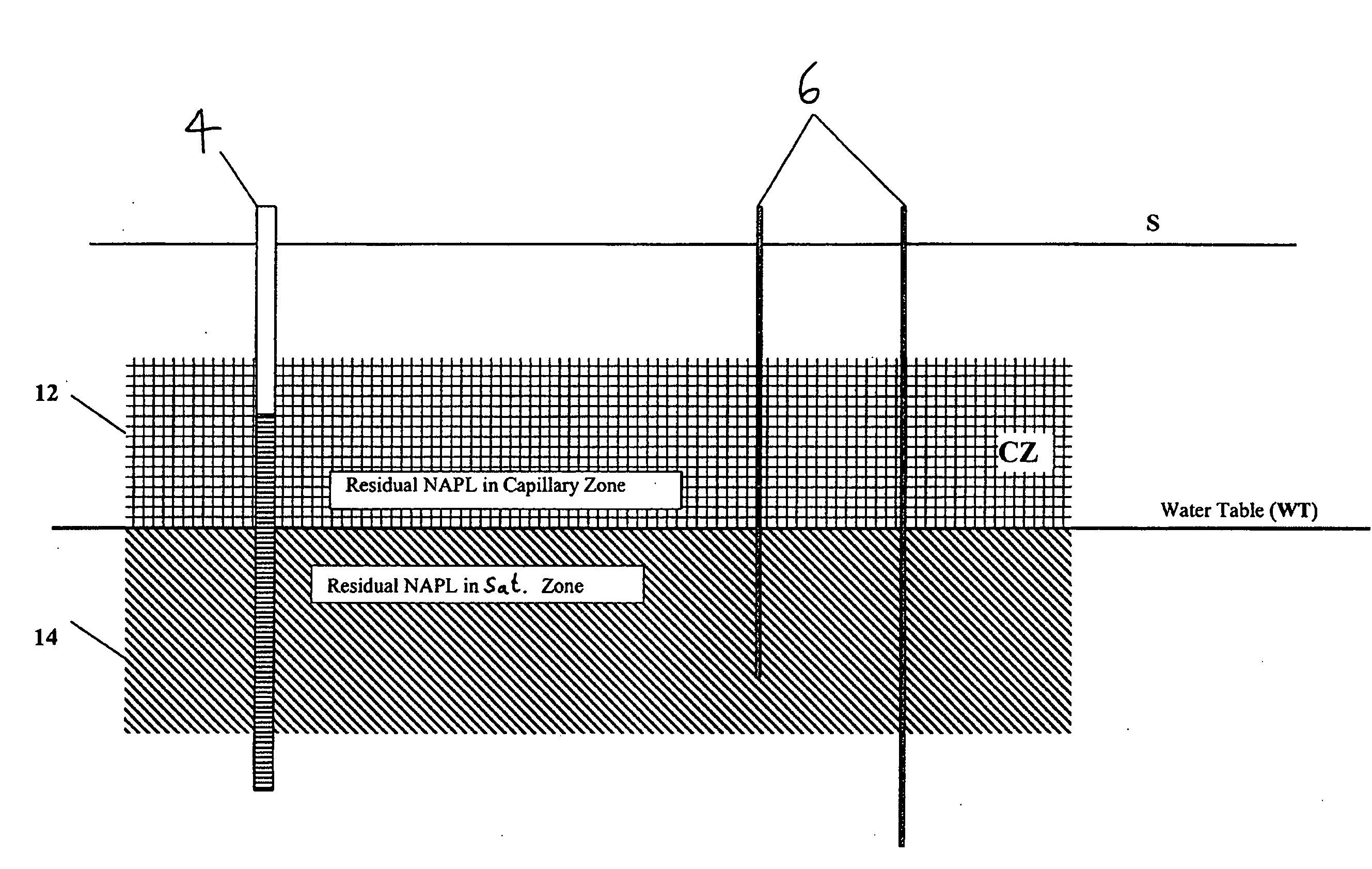
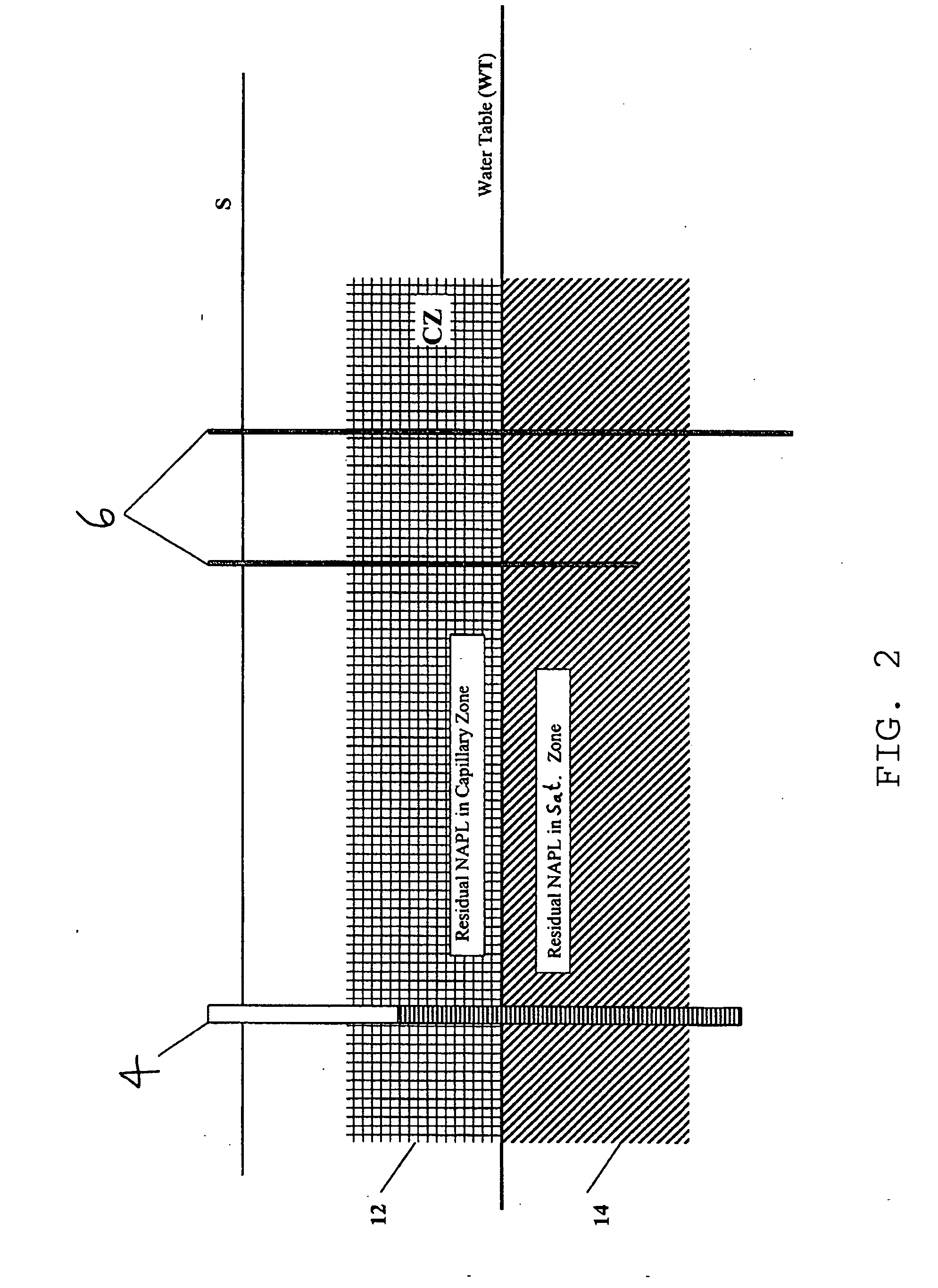
[0070] Static LNAPL thickness, T, decreases in well after estimate pulsing for a given duration.[0071]i. Measure the stabilized decrease in NAPL thickness in a monitoring well.[0072]ii. Subtract this thickness from the original entry pressure ρow value obtained from the laboratory (or literature value) for this parameter.[0073]iii. Insert this value into equation (1) and re-compute Tnew Calculate

T0−Tnew=ΔT [0074]ΔT corresponds to a new capillary pressure and NAPL retention function, which in turn corresponds to the amount of residual now available for recovery. Refer to FIG. 6.[0075]iv. Apply Step 2 to ΔT and re-calculate the new recoverable volume. The difference between the original volume and the new volume is the residual volume / mass available for removal.

[0076]The operating principal in Case 1 is that the SPT process stresses the soil / rock matrix and causes the pore bodies and pore throats to expand and increase their interconnectivity. The soil / rock matrix consists of pore bod...

case 2

[0078] Static LNAPL thickness, T, increases in well after test pulsing for a given duration.[0079]i. Measure the stabilized increase in LNAPL thickness. This increase above the static level is taken to be the new estimate of ρow.[0080]ii. Add this thickness to the original ρow value obtained from the laboratory (or literature value) for this parameter.[0081]iii. Insert this value into equation (1) and re-compute Tnew [0082]iv. Calculate

Tnew−T0=ΔT [0083]v. Apply Step 2 to ΔT and re-calculate the new recoverable volume. The difference is the amount of residual volume / mass removed.

[0084]The operating principal in Case 2 is identical to that in Case 1 except that the pore throat to pore body ratio is not increased significantly, or quickly enough, so that PC remains less than or equal to the entry (displacement) pressure ρow. In this instance, NAPL accumulates in the well from mobilized residual in response to pulsing and the thickness increases. The increase in NAPL thickness above sta...


PUM

PropertyMeasurementUnit
volumeaaaaaaaaaa
thicknessaaaaaaaaaa
stressaaaaaaaaaa

Abstract

A remediation process that a employs improved quantitative method(s) of estimating of the volume and/or mass of contaminant in the subsurface, removal and or in situ degradation of the contamination using subsurface pulsing treatment (“SPT”) technology, and evaluation of the degree of remediation by re-applying the quantitative contaminant evaluation methods. The process uses SPT technology with the addition of a vacuum or sub-atmospheric pressure to an extraction well in order to create a push-pull effect to remove free contaminant or residual in conjunction with the pressure wave driving force created in the excitation or excitation well. The process can quantitatively measure the amount of residual contaminant, which up until now has not been possible or tractable using in situ methods, as well as measure the amount of residual that can be removed by SPT.

Description

FIELD OF THE INVENTION[0001]This mechanical process involves propagating subsurface pressure (excitation) waves that strain elastic porous media or fractured geologic media such that the induced pressure wave energy increases pore space, voids, or aperture size. The pressure waves promote a dynamic porosity that also increases pore size and interconnectivity and simultaneously causes fluids to both dispense and disperse, and otherwise mobilize and flow. The process also causes residual fluids to flow and this is currently the only known method to have this effect on a range of geologic media. Collectively, the described flow effects are known as subsurface pulsing treatment (SPT). SPT is utilized to more accurately estimate the volume and / or mass of recoverable residual non-aqueous phase liquids (“NAPL”). One known means for propagating subsurface pressure waves is through the equipment and science disclosed in U.S. Pat. Nos. 6,241,019; 6,405,797; 6,851,473 and U.K. Patent Number 23...

Claims


Application Information

Patent Timeline
Patent Type & Authority Applications(United States)
IPC IPC(8): B09C1/00E21B47/00E21B43/00C02F1/00
CPCB09C1/002B09C1/02E21B47/18B09C2101/00C02F2103/06B09C1/08
Inventor PANTER, STEVEN
Owner REMMETRIK
Why Eureka
Try Eureka