Sample hold circuit for use in time-interleaved a/d converter apparatus including paralleled low-speed pipeline a/d converters
a technology of time-interleaved a/d converter and sample hold circuit, which is applied in the direction of pulse manipulation, pulse technique, instruments, etc., can solve the problems of series connection addition, significant deterioration of the performance of the time-interleaved a/d converter, etc., to achieve the effect of reducing the clock skew, increasing the chip area and small area
- Summary
- Abstract
- Description
- Claims
- Application Information
AI Technical Summary
Benefits of technology
Problems solved by technology
Method used
Image
Examples
Embodiment Construction
[0052]Preferred embodiments of the present invention will be described with reference to the drawings. In the following preferred embodiments, like components are denoted by like reference numerals.
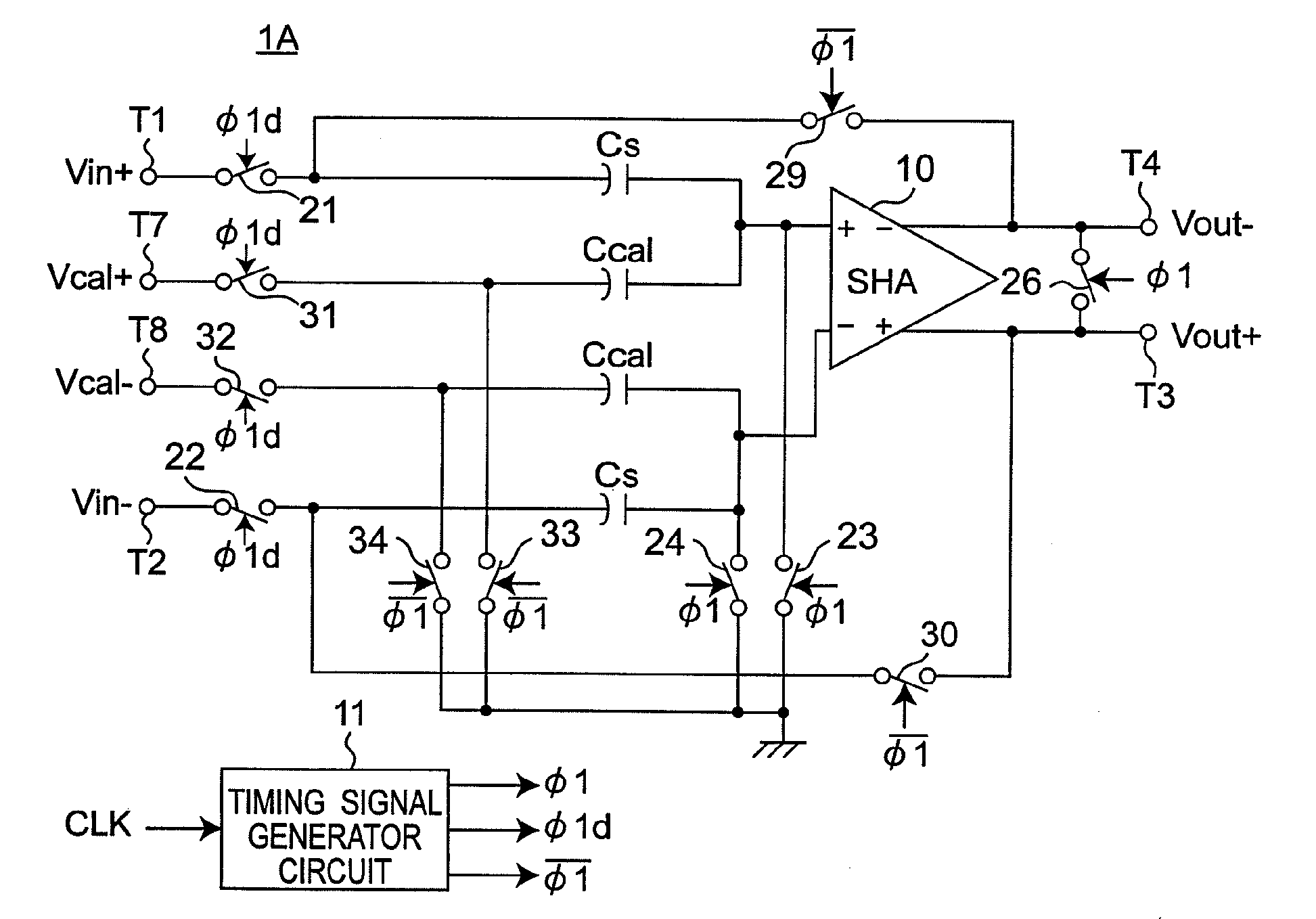
[0053]FIG. 6 is a timing chart showing an operation in presence and absence of skew in an A / D converter according to one preferred embodiment of the present invention. FIG. 7 is a block diagram showing a configuration of a sample hold circuit 1A for use in the A / D converter of the present preferred embodiment, and
[0054]FIG. 8 is a timing chart showing timing signals φ, φ1d, and φ1 generated by the timing signal generator circuit 11 of FIG. 7.
[0055]In the preferred embodiment of the present invention, a novel practical adder circuit (see FIGS. 7, 10, and 11) of a calibration signal for use in the sample hold circuit of the A / D converter apparatus. Referring to FIG. 6, a clock skew amount (in FIG. 6, Vcal,m (m=1, 2, . . . , M) is a detected voltage corresponding to the clock skew amount) is...
PUM
 Abstract
Description
Claims
Application Information
 - R&D
- Intellectual Property
- Life Sciences
- Materials
- Tech Scout
- Unparalleled Data Quality
- Higher Quality Content
- 60% Fewer Hallucinations
Browse by: Latest US Patents, China's latest patents, Technical Efficacy Thesaurus, Application Domain, Technology Topic, Popular Technical Reports.
© 2025 PatSnap. All rights reserved.Legal|Privacy policy|Modern Slavery Act Transparency Statement|Sitemap|About US| Contact US: help@patsnap.com


