Self-rotating deployed film solar batteries array and its use in space
a solar battery array and self-rotating technology, applied in the field of self-rotating deployed film solar batteries array and its use in space, can solve the problems of endangering rotating tensile, and achieve the effects of enhancing the ability to maintain on orbit, enhancing maneuverability, and enhancing power
- Summary
- Abstract
- Description
- Claims
- Application Information
AI Technical Summary
Benefits of technology
Problems solved by technology
Method used
Image
Examples
implementation example 1
A Batteries Array is Made of Rectangle Film Solar Batteries
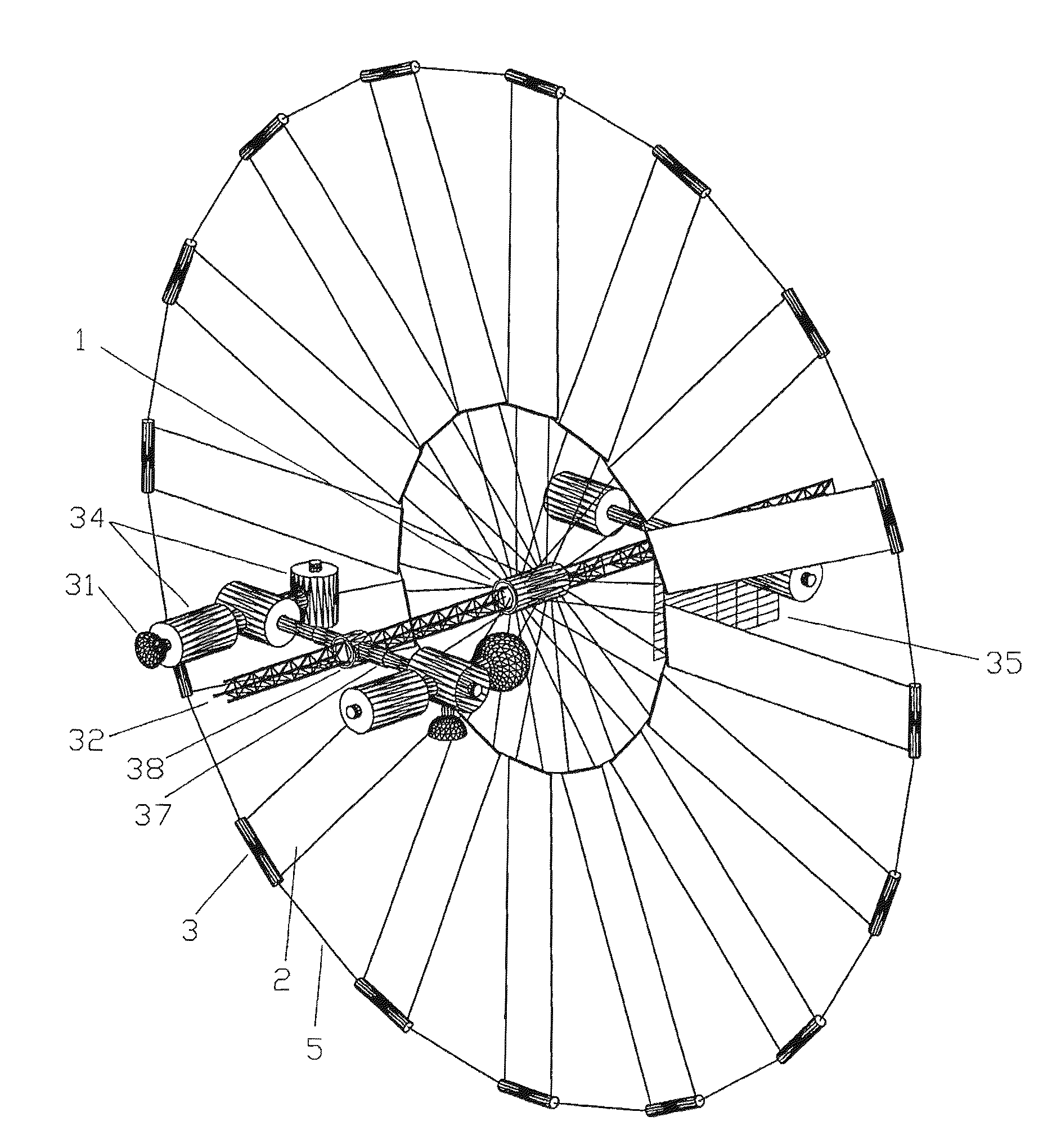
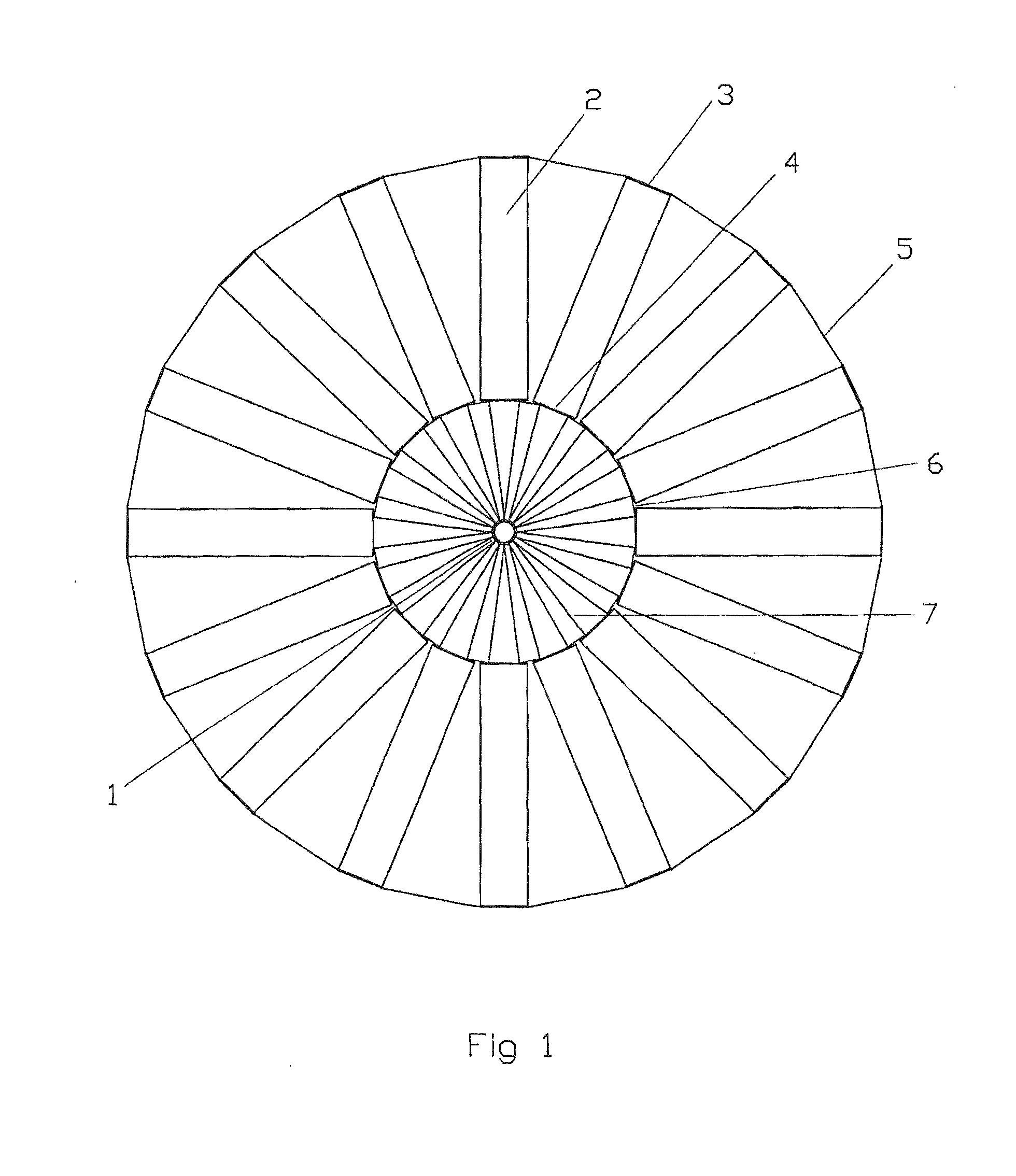
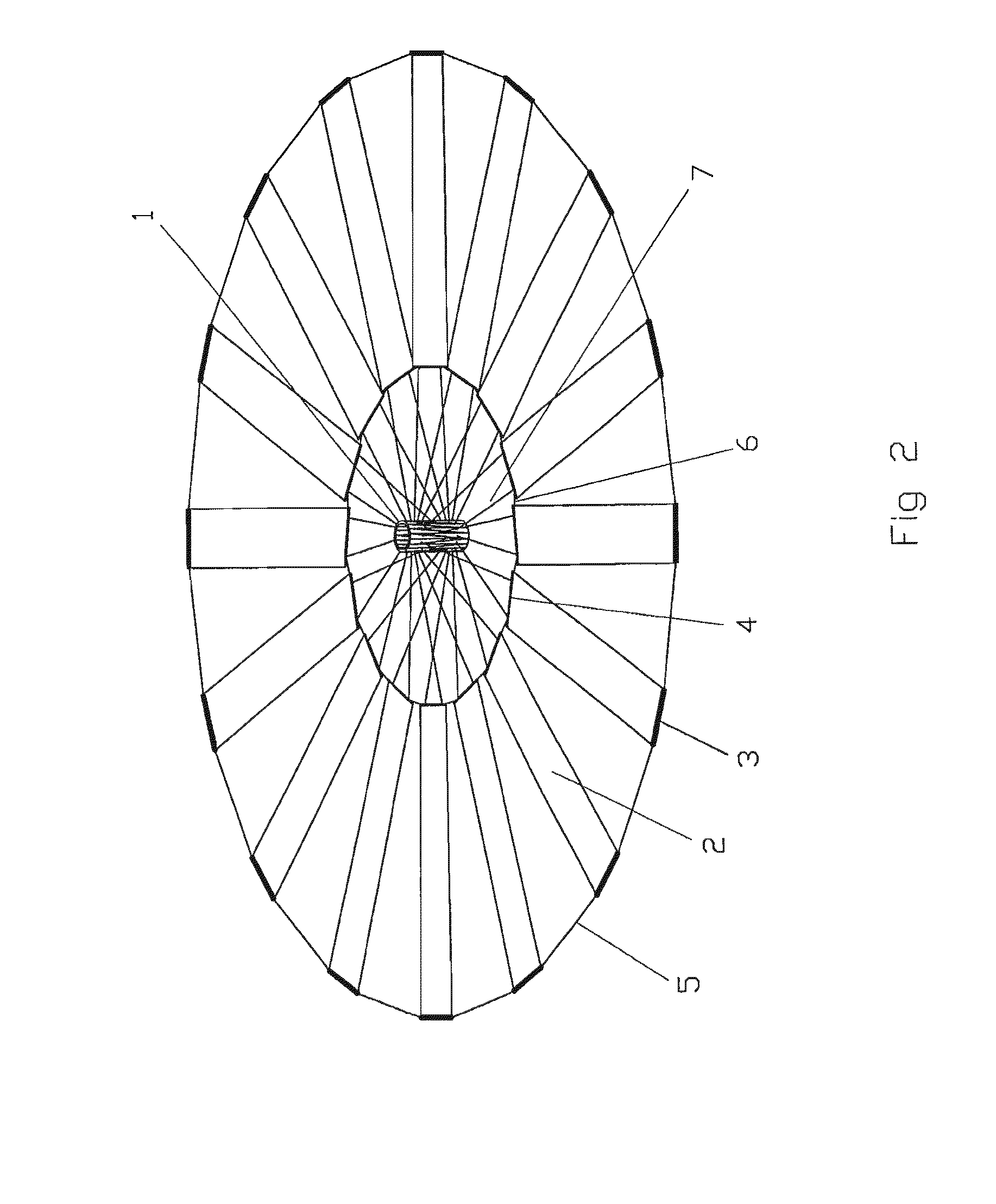
[0040]FIG. 1 shows top-view of a completely deployed rectangular thin film batteries array. The center axle (1) located at the middle batteries array. The thin film batteries (2) (16 spokes) radiates out to form a circular shaped array. The neighboring thin film batteries are connected with outside ring cable (5) and inside ring cable (6). Near the center array, one end of each thin film batteries array connects the center axle (1) with electrical cable (7) (this example has 32 cables). The thin film battery (2) has outside reinforcing rod (3) and inside reinforcing rod (4) at both end, used to protect the thin film battery and control thin film's direction. FIG. 2 is a three-dimensional schematic drawing for the thin film solar batteries array described above, (All attached numbering figures are consistently used in this instruction booklet. The name of various components in the figure are not given unnecessary details.) FI...
implementation example 2
A Batteries Array Constructed by Fan-Shaped Thin Film Batteries
[0048]FIG. 3 shows the front-view of a completely deployed fan-shaped thin film batteries array: the fan-shaped thin film solar batteries (8) spoke to form a circular. The neighboring thin film batteries are connected with outer ring (5) and inner ring cable (6). Near the center of the array, the thin film battery has inside reinforcing rod (4). Both sides of reinforcing rod has electrical cable (7) connecting to the center axle (1). (Because two end sides of neighboring inside reinforcing rods are too close, electrical cables leading out from two ends form a y-shaped connecting cable which in FIG. 3 shows.
[0049]FIG. 4 is a completely deployed three-dimensional schematic drawing of a fan-shaped thin film batteries array: obviously unlike a rectangular thin film batteries array, electrical cable (7) is completely set in a plane with the thin film battery, therefore the thin film battery inclining angle is unable to adjust...
implementation example 3
The Plan to Reduce Center Axle Diameter
[0051]In the most situations, a center axle certainly is not a spacecraft's main body. Fitting into a spacecraft to carry before lifting off, a thin film batteries array should minimize its size by reducing the diameter of the center axle as much as possible. When the center axle diameter is 5% smaller than the thin film batteries array's diameter after its deployment, the control to the thin film batteries array action is very weak. In order to solve this problem, it may use one kind of structure similar to umbrella skeleton inside the center axle. Like FIG. 11 shows: the center axle (43) exterior is a tall and slender cylindrical shell, the umbrella column (44) passing through the center of the center axle (43), setting with an upper plate at its top (18), the umbrella bone (19) connecting to the upper plate (18) with a hinge joint, and the electrical cable plate (10) is harnessed on the axle of the hinge. The umbrella bone (19) is a hollow t...
PUM
 Abstract
Description
Claims
Application Information
 - R&D
- Intellectual Property
- Life Sciences
- Materials
- Tech Scout
- Unparalleled Data Quality
- Higher Quality Content
- 60% Fewer Hallucinations
Browse by: Latest US Patents, China's latest patents, Technical Efficacy Thesaurus, Application Domain, Technology Topic, Popular Technical Reports.
© 2025 PatSnap. All rights reserved.Legal|Privacy policy|Modern Slavery Act Transparency Statement|Sitemap|About US| Contact US: help@patsnap.com


