Distillation apparatus

a technology of distillation apparatus and vaporizer, which is applied in the direction of vacuum distillation separation, lighting and heating apparatus, separation processes, etc., can solve the problems of unstable cooling water temperature, rust or scale, and freezing of water, so as to reduce the cost and time of maintenance, reduce the formation of rust, and efficiently cool the vapor

Active Publication Date: 2009-11-19
QINGDAO HAIER WASHING MASCH CO LTD +1
View PDF14 Cites 4 Cited by
  • Summary
  • Abstract
  • Description
  • Claims
  • Application Information

AI Technical Summary

Benefits of technology

[0037]Thus, the distillation apparatus according to the first aspect of the present invention can efficiently cool vapor of a solvent or similar liquid without using cooling water and collect the condensed solvent in a liquid state. The disuse of water prevents the formation of rust or scale due to a long-term use, the freezing of water in cold climates and other problems and hence reduces the cost and time for the maintenance. The cooling process can always be efficiently performed with little influence from ambient temperatures, so that the distillation rate of the liquid to be processed will be improved.
[0038]The distillation apparatus according to the second aspect of the present invention can be downsized for a higher degree of installation freedom and yet efficiently perform the cooling process to improve the distillation rate of the liquid to be processed.

Problems solved by technology

However, it also has various problems, such as the formation of rust or scale due to a long-term use, the freezing of water in cold climates, and the cooling water's temperature being unstable due to the influence of ambient temperature in the case of a cooling tower.
There are also many inconveniences relating to maintenance.
This means that a cooling container for condensing the solvent vapor must be provided separately from the buffer tank, which impedes the downsizing of the apparatus.
However, there is also the problem that the temperature of the solvent in the buffer tank is higher than that of the cooling water and hence it is difficult to ensure a large temperature difference between the solvent and the solvent vapor, which leads to inadequate cooling of the solvent vapor and inappropriate condensation thereof.
Another problem is that a large capacity buffer tank is required because the solvent in the buffer tank needs to have a large heat capacity.

Method used


Image

  • Distillation apparatus
  • Distillation apparatus
  • Distillation apparatus

Examples


Embodiment Construction

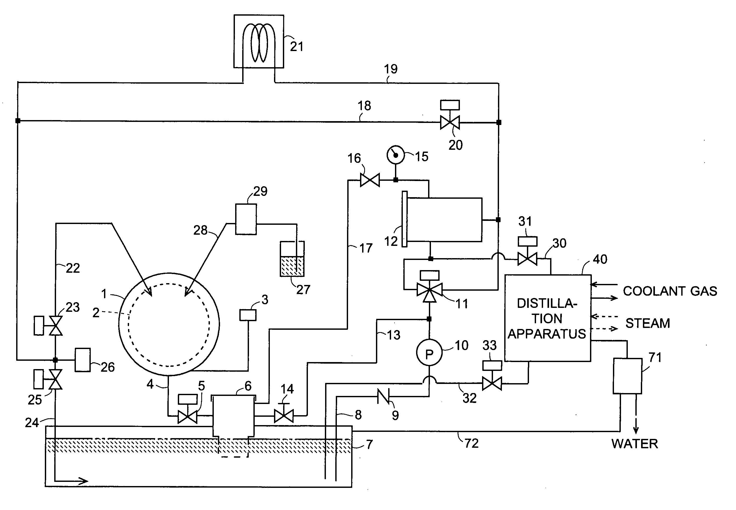
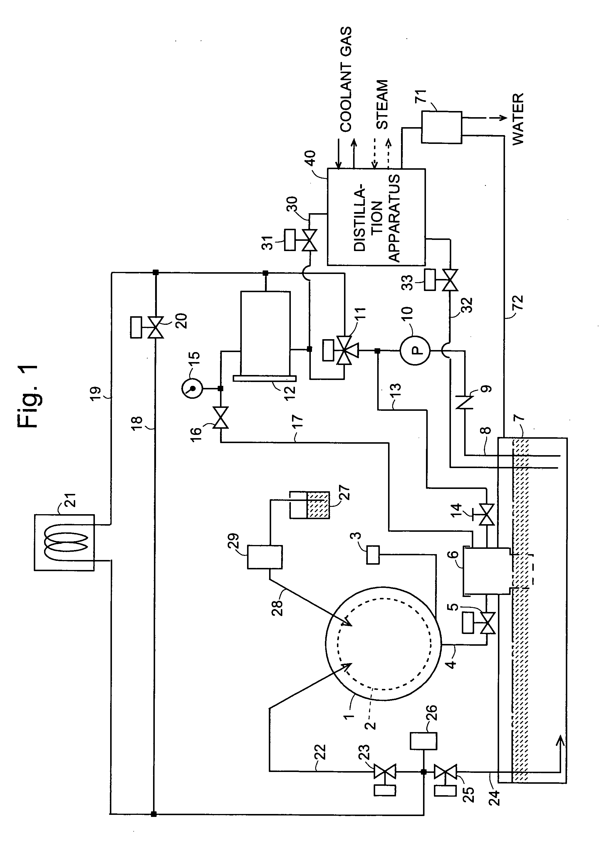
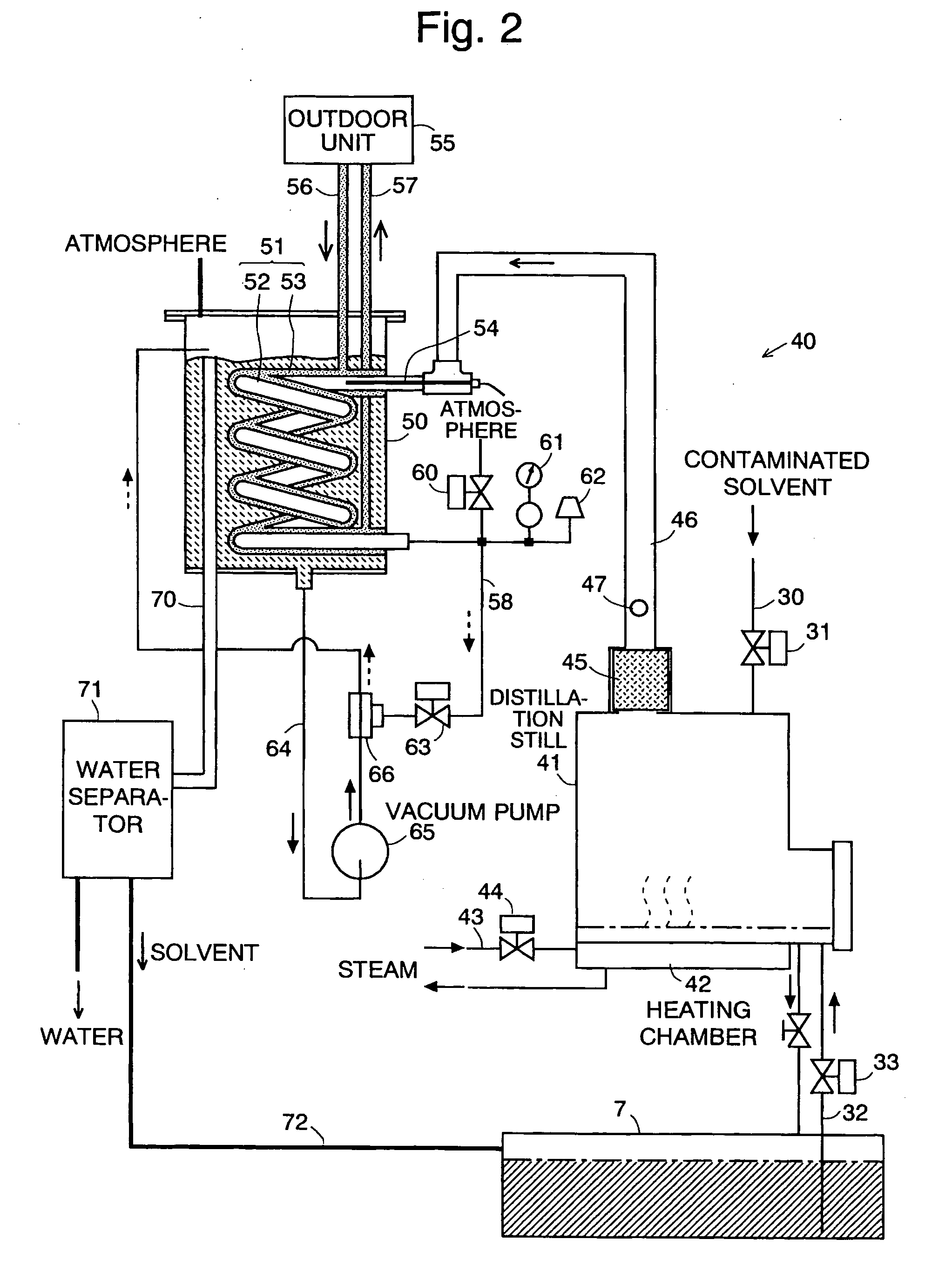
[0071]One embodiment of the present invention, which is a distillation apparatus used in a dry cleaner, is hereinafter described with reference to FIGS. 1 and 2. FIG. 1 is a configuration diagram showing the pipe arrangement and other important components of the dry cleaner using the distillation apparatus in the present embodiment, and FIG. 2 is a configuration diagram showing the pipe arrangement and other components of the distillation apparatus in the present embodiment. The following description assumes that the liquid to be processed in the present invention is a solvent used in the cleaning operation of the dry cleaner, such as a petroleum solvent or silicon solvent.

[0072]In FIG. 1, the dry cleaner has an outer tub 1, in which a cylindrical drum 2 having a large number of liquid-passing holes formed in its circumferential wall is supported by a shaft in a free-to-rotate manner. The outer tub 1 can store a solvent, whose level can be detected by a level sensor 3. A drainage li...


PUM

PropertyMeasurementUnit
temperatureaaaaaaaaaa
surface areaaaaaaaaaaa

Abstract

A spiral double-tube structure including an inner tube for introducing a solvent vapor resulting from vaporization within a distillation still and an outer tube which a coolant gas cooled by an outdoor machine is passed through is disposed in a buffer tank; the solvent vapor is directly cooled from the surrounding area by the coolant gas with a large temperature difference and thus condensed into a liquid state; by means of an ejector, the liquid is mixed with the solvent suctioned from the buffer tank and returned into the buffer tank; since the solvent in the buffer tank is also directly cooled by the coolant gas, the cooling efficiency is high; accordingly, both the solvent vapor generated from the distillation still and the solvent in the buffer tank for reducing the pressure inside the distillation still can be efficiently cooled without using cooling water, and downsizing of the apparatus can also be attained.

Description

TECHNICAL FIELD[0001]The present invention relates to a distillation apparatus for purifying a solvent used in a dry cleaner or a solvent used for cleaning various electronic components.BACKGROUND ART[0002]In a dry cleaning machine used in cleaners and similar establishments, a vacuum distillation apparatus for purifying a solvent is employed to reuse a solvent (silicon oil, petroleum solvent and the like) contaminated as a result of cleaning laundry. Currently, such a distillation apparatus generally uses a solvent vapor condensation method in which a spiral pipe or similar pipe having a large surface area is disposed within a container filled with a solvent vapor, and water that has been cooled by a chiller or cooling tower is passed through the pipe to condense the vapor (for example, refer to Patent Document 1). Another method uses the same system in a reverse way: the container with the spiral pipe disposed therein is filled with cool water, and a solvent vapor is passed throug...

Claims


Application Information

Patent Timeline
Patent Type & Authority Applications(United States)
IPC IPC(8): B01D3/04F28D7/10B01D3/00
CPCB01D1/0047B01D3/10B01D5/0006D06F43/081B01D5/006B01D5/009B01D5/0045D06F43/00D06F43/08
Inventor NORO, MASARUNAKAGAWA, KATSUHITO
Owner QINGDAO HAIER WASHING MASCH CO LTD
Why Eureka
Try Eureka