[0012]
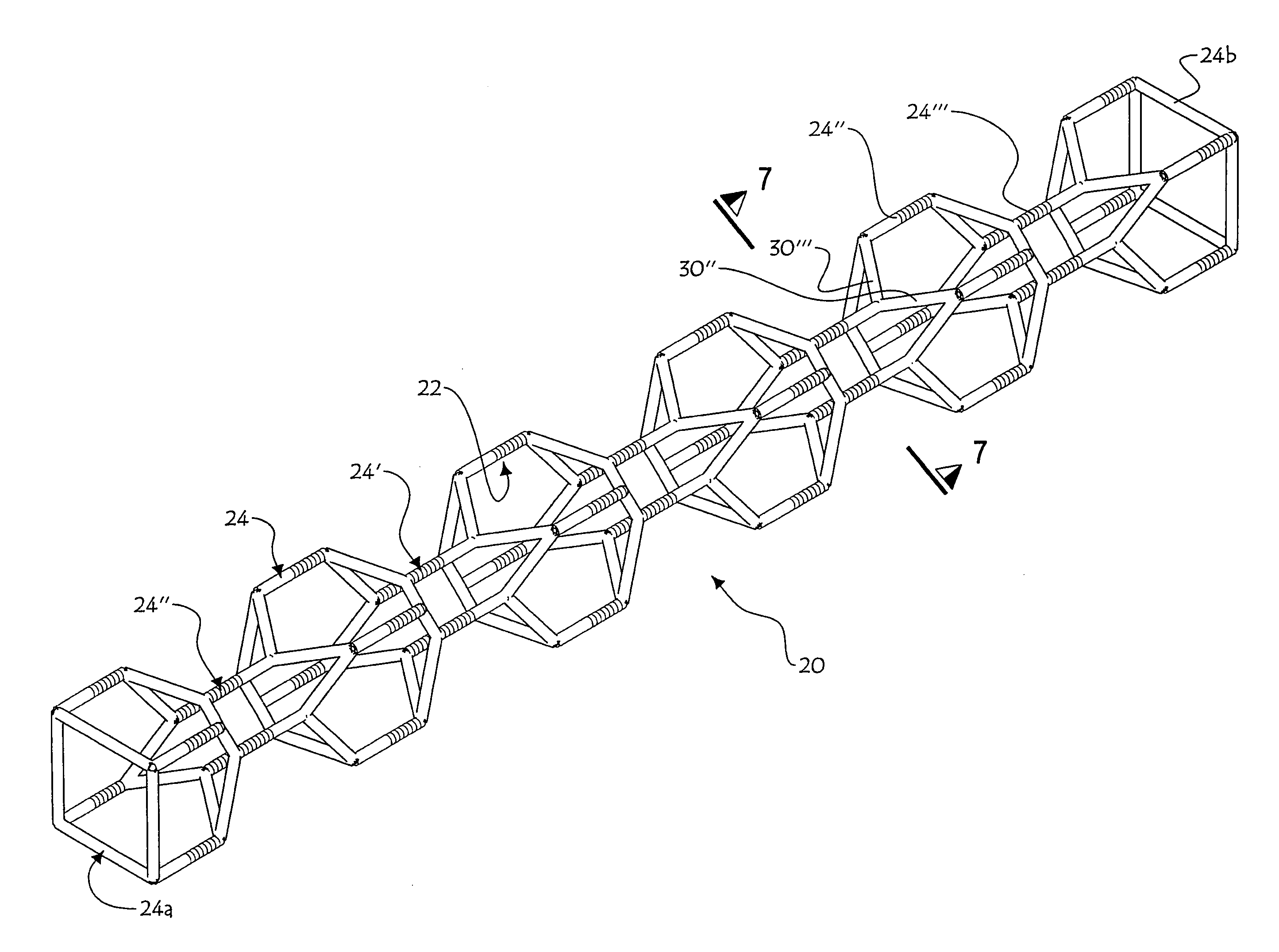
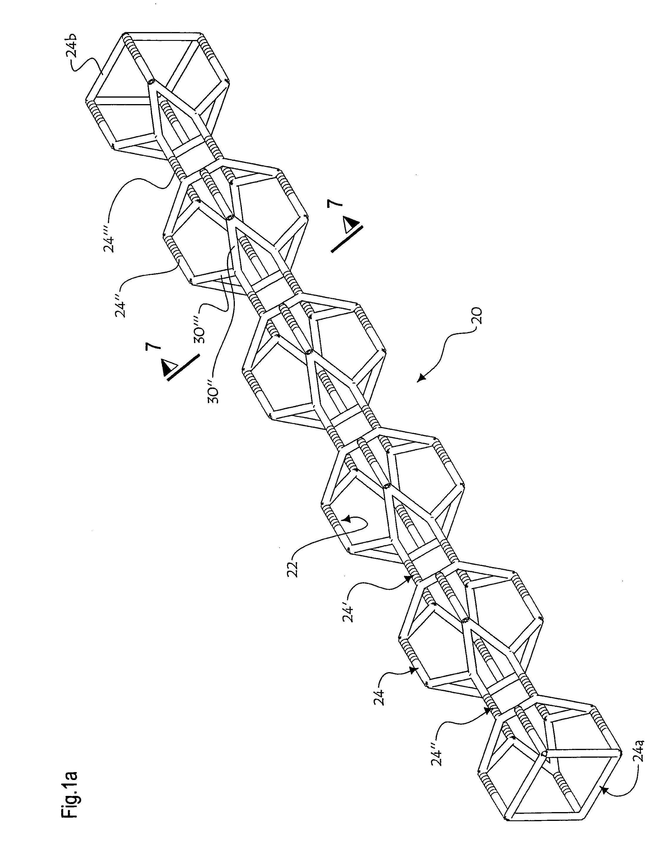
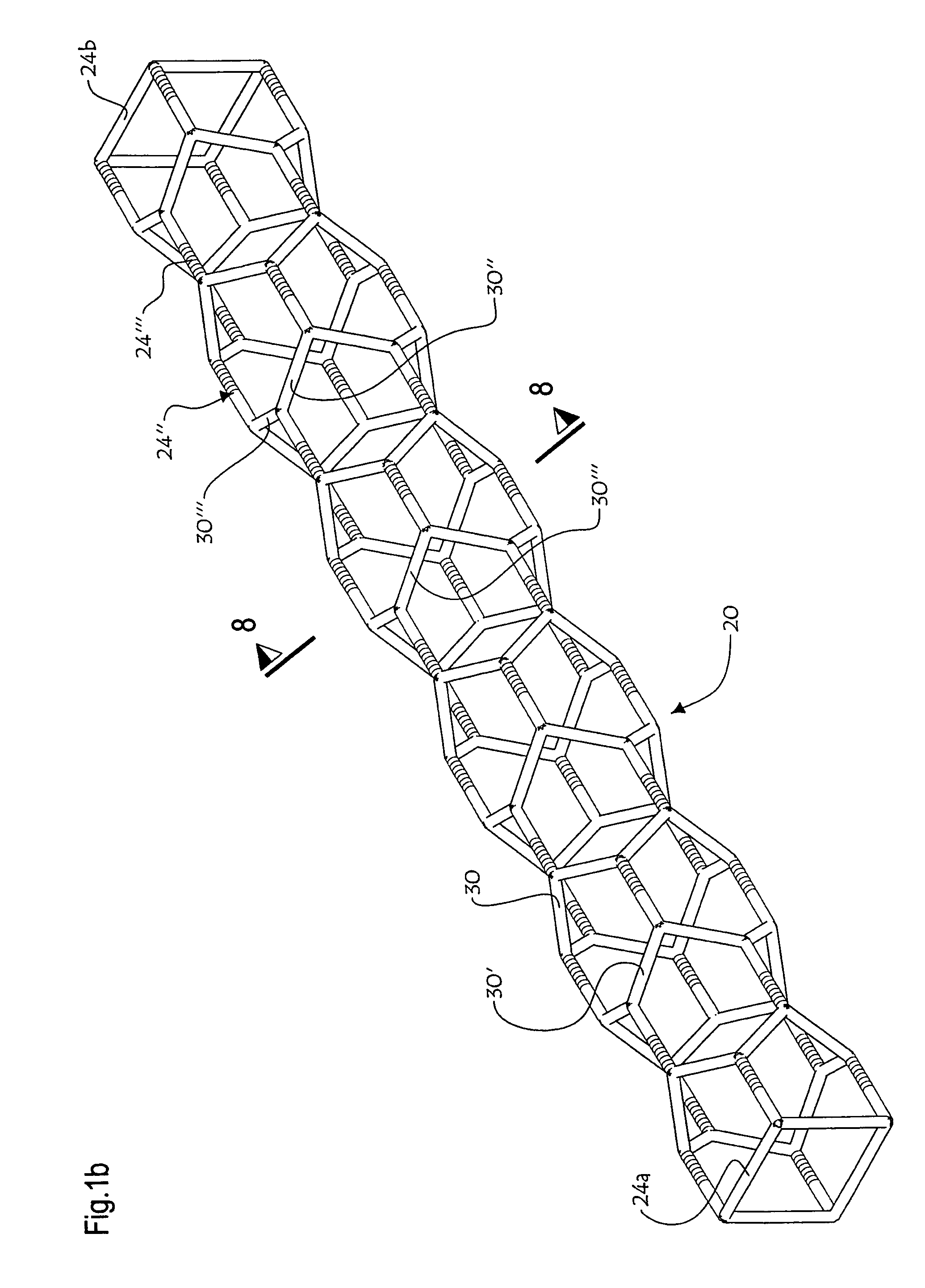
Stent design according to the invention is such that axial polarization magnets are used, i.e. magnets with polarization being orthogonal to the stent
radius, and thus parallel to the
long axis of the
blood vessel. This specific
layout of magnets (which are preferably cylindroid) enables procurement of a compressed
diameter as small as possible, an important consideration to promote percutaneous stent engagement before radial expansion thereof. Moreover, it is noted that a small
angular deviation (small
acute angle) between the
long axis of the cylindroid magnets and the
long axis of the registering blood vessel, would still make the present invention operative, i.e. the
magnetic field interaction from the multiple magnets
layout would still enable radial expansion of the present stent tubular body. These magnets are arranged in rows, each row made up of a minimum of three (3) magnets, which are placed
equidistant to one another along a circumference of this row. All adjacent poles of magnets from a same row are of the same type, for example, “+” side closely spaced to a “+” side.
[0013]The next row consists of the same number of axial polarization magnets as the preceding one, being
equidistant relative to one another along this row circumference. All adjacent poles of magnets of this row are also of the same type, for example, “−” side closely spaced to a “−” side. On the other hand, the orientation of these magnets polarity is the opposite to that of the preceding row, wherein all poles spacedly facing each other are of the same type. This specific configuration of polarity between magnets from adjacent rows facing spacedly from each other enables avoidance of self collapse of the stent. Moreover, the position of each
magnet of this row at the level of the circumference is such that each
magnet of the second row is preferably exactly in between those of the preceding row. This latter configuration in turn provides an optimal distribution of the support on all the circumference of the blood vessel wall where the stent is applied.
[0021]In accordance with a first embodiment of the invention, there is provided a two-layer tubular flexible stent sheath, defining a first radially outward layer and a second radially inward layer. The
diameter of the sheath after magnetic expansion is slightly greater than the optimal functional diameter of the blood vessel section into which the stent is installed, to ensure friction fit stable positioning thereof and prevent accidental shifting with time along the blood vessel.
[0022]To install this
two layer flexible sheath stent, there may be used a cylindroid
catheter inserted non-invasively through a small puncture made in the
skin and in the blood vessel distally from the stenosed blood vessel segment. The patient does not need to be asleep during this intervention, as local anesthetics are usually sufficient The grips of the
catheter with metallic guide wire grabs the present stent at the leading end thereof and maintains the tubular body thereof in a radially inward inoperative condition, diametrally smaller than the lumen of the blood vessel, against the radially outward
resultant bias of the magnets array. The stent at the leading end of the
catheter is pushed along the blood vessel, until the stent comes in transverse register with the stenosed segment of this blood vessel. At this point, the catheter grips release their grip on the stent main body, thus enabling the stent magnets array to transform magnetic repulsion forces into a radially outwardly
mechanical force onto the stent flexible main body, up to its radially outwardly expanded operative stable limit condition.
[0023]The two
layers of the stent sheath may be attached to one another for example by glue, by stitching, or even fused to one another, when the stent is made, except for the discrete areas forming the
magnet receiving pockets. The magnets will then be trapped between the unattached portions of two
layers of the stent sheath in closely spaced fashion—think ravioli pasta, and their meat receiving pockets. Each sheath main body pocket is sized and shaped to complementarily receive one magnet, so that the magnet will remain stationary: in particular, accidental translational,
yaw or tilt motion should be prevented, and also rotational motion in the case of bar magnets, so as to constantly maintain the same
magnetic field orientation.
[0026]In this alternate embodiment of stent, the size of the magnet pockets is reduced to the smallest possible, as well as the size of the mesh providing
structural integrity between each pair of closely spaced magnets, wherein the overall diameter thereof in its radially inward limit position is as compact as possible to facilitate this stent installation through the blood vessel lumen. Accordingly, the radially inward limit diameter of this stent should be substantially smaller than that of the first hereinabove embodiment. A major portion of the tubular lattice will therefore be modified to make it hollow. Inner pockets each having a size and shape complementary to a given cylindroid magnet, will be provided, such that each magnet will remain taut in place in its corresponding pocket while being prevented from accidental tilting,
yaw or
translational motion. The relative position of these magnets holding pockets, and the relative orientation of the magnets inside their respective pockets, will generate
dipole moments between closely spaced pairs of magnets that will bring about a
resultant vector of
mechanical force consisting of a radially expanding biasing force on the overall flexible tubular lattice toward a stable expanded condition.


