Hydrodynamic bearing device and spindle motor using the same

a technology of hydrodynamic bearing and spindle motor, which is applied in the direction of sliding contact bearings, mechanical instruments, mechanical equipment, etc., can solve the problems of insufficient reliability of the device, shortened service life of the device, and evaporation of lubricant, etc., to achieve excellent heat resistance and low-temperature fluidity, high reliability, and high performance of the hydrodynamic bearing

Active Publication Date: 2009-11-26
PHC HLDG CORP
View PDF13 Cites 2 Cited by
  • Summary
  • Abstract
  • Description
  • Claims
  • Application Information

AI Technical Summary

Benefits of technology

[0011]The lubricant for the hydrodynamic bearing device contains diesters obtained from a divalent alcohol having 4 to 8 carbon atoms and having no alkyl side chain at the β position and one or more kinds of saturated monovalent fatty acids having 9 to 13 carbon atoms. Hence, its viscosity is low in comparison with conventional lubricants, and it is possible to realize a hydrodynamic bearing device being low in torque. In addition, the heat resistance of the lubricant is high, and the amount of evaporation can be reduced; hence, the amount of the lubricant applied to one device is reduced, and the cost can be reduced and the device can be miniaturized. With the configuration of the present invention, it is possible to realize a hydrodynamic bearing device being low in torque, low in power consumption, high in reliability and suited for miniaturization.
[0042]As the hydrodynamic bearing device and the spindle motor using the same in accordance with the present invention, it is possible to realize a hydrodynamic bearing device being low in torque, low in power consumption, high in reliability and suited for miniaturization and a spindle motor using the same by using a lubricant being low in viscosity and excellent in heat resistance.

Problems solved by technology

However, in these conventional examples of hydrodynamic bearing devices, although the torque can be reduced, such problems are caused that the amount of evaporation of the lubricant increases since the heat resistance of the lubricant is low, the service life of the device is shortened, and the reliability of the device cannot be obtained sufficiently.
In addition, in the case that a more than necessary amount of the lubricant is applied in consideration of the amount of evaporation of the lubricant, such problems are caused that increase in torque and increase in cost are caused corresponding to the amount, and miniaturization becomes difficult since it is necessary to obtain space.

Method used


Image

  • Hydrodynamic bearing device and spindle motor using the same
  • Hydrodynamic bearing device and spindle motor using the same
  • Hydrodynamic bearing device and spindle motor using the same

Examples


embodiment 1

[0051]Embodiment 1 of the present invention will be described with reference to FIG. 2.

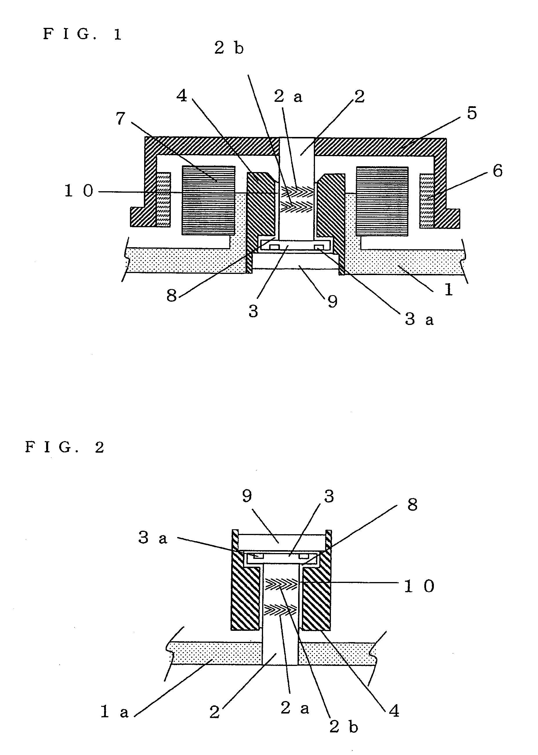
[0052]FIG. 2 is a schematic cross-sectional view showing a shaft-fixed type hydrodynamic bearing device. In FIG. 2, a base 1 a, a shaft 2, radial dynamic pressure generation grooves 2a and 2b, a thrust flange 3, a thrust dynamic pressure generation groove 3a, a sleeve 4, a lubricant 8, a thrust plate 9 and a radial clearance 10 are shown.

[0053]The thrust flange 3 is fixed at one end of the shaft 2, on the outer peripheral surface of which the radial dynamic pressure generation grooves 2a and 2b being herringbone-shaped are formed, whereby a shaft section is formed. The other end of the shaft 2 is press-fitted in and fixed to the base 1a. The shaft section is inserted into the bearing hole of the sleeve 4, and the thrust plate 9 is installed in the sleeve 4 so as to be opposed to the thrust flange 3 and to block one side of the bearing hole. In addition, the thrust dynamic pressure generation groov...

embodiment 2

[0071]Embodiment 2 of the present invention will be described with reference to FIG. 2 again. This embodiment is similar to Embodiment 1 except for the difference in the ingredients of the lubricant 8.

[0072]The lubricant 8 differs from the lubricant 8 in accordance with Embodiment 1 in that esters obtained from a divalent alcohol having 4 to 8 carbon atoms and having no alkyl side chain at the β position, a saturated dibasic acid having 6 to 10 carbon atoms and a saturated monovalent fatty acid having 5 to 13 carbon atoms are used instead of a diester obtained from a divalent alcohol having 4 to 8 carbon atoms and having no alkyl side chain at the β position and a saturated monovalent fatty acid having 9 to 13 carbon atoms. In other respects, the lubricant 8 is similar to the lubricant 8 in accordance with Embodiment 1.

[0073]Esters obtained from a divalent alcohol having 4 to 8 carbon atoms and having no alkyl side chain at the β position, a saturated dibasic acid having 6 to 10 car...

embodiment 3

[0080]Embodiment 3 of the present invention will be described with reference to FIG. 1.

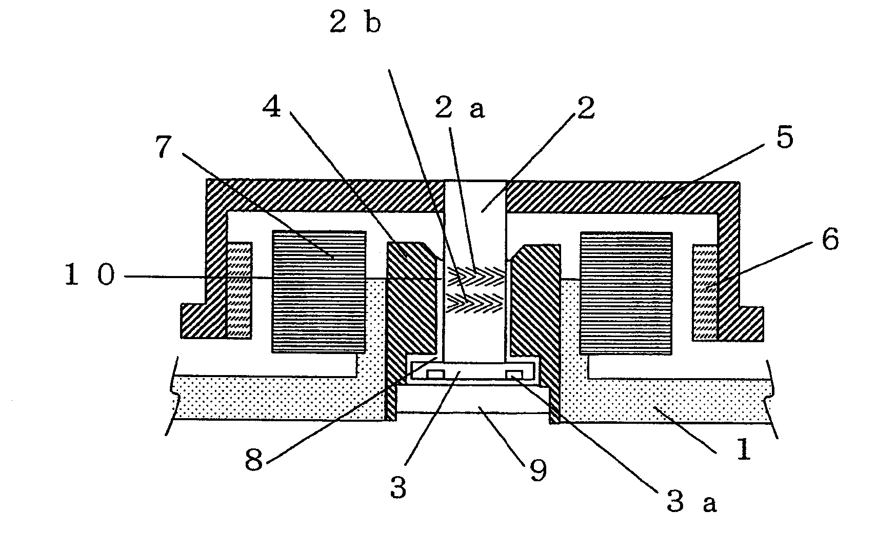
[0081]FIG. 1 is a cross-sectional view showing a spindle motor having a shaft-rotation type hydrodynamic bearing device in accordance with Embodiment 3. The hydrodynamic bearing device in accordance with this embodiment differs from the hydrodynamic bearing device shown in FIG. 2 in that the hydrodynamic bearing device is changed from a shaft-fixed type to a shaft-rotation type, that a base 1 is provided instead of the base 1a, and that a hub 5, a rotor magnet 6 and a stator coil 7 are provided. In other respects, this embodiment is similar to Embodiment 1; components having similar or equivalent configurations are designated by the same numerals, and their detailed descriptions are omitted.

[0082]A thrust flange 3 is fixed at one end of a shaft 2, on the outer peripheral surface of which herringbone-shaped radial dynamic pressure generation grooves 2a and 2b are formed, and the hub 5, on which mag...


PUM

PropertyMeasurementUnit
temperatureaaaaaaaaaa
viscosityaaaaaaaaaa
viscosityaaaaaaaaaa

Abstract

A hydrodynamic bearing device being low in torque, low in power consumption, high in reliability and best suited for miniaturization and a spindle motor using the same.The hydrodynamic bearing device in accordance with the present invention, dynamic pressure generation grooves being provided on at least one of a shaft or a sleeve, and a lubricant being present in a clearance where the above-mentioned shaft and the above-mentioned sleeve are opposed to each other, is characterized in that the above-mentioned lubricant contains diesters obtained from a divalent alcohol having 4 to 8 carbon atoms and having no alkyl side chain at the β position and one or more kinds of saturated monovalent fatty acids having 9 to 13 carbon atoms.

Description

CROSS-REFERENCE TO RELATED APPLICATIONS[0001]This application is a divisional of copending U.S. patent application Ser. No. 11 / 092,186, filed Mar. 29, 2005, the disclosure of which is incorporated herein by reference.BACKGROUND OF THE INVENTION[0002]The present invention relates to a dynamic-pressure type hydrodynamic bearing device and a spindle motor using the same.[0003]A hydrodynamic bearing comprises a shaft and a sleeve for supporting the shaft, and a lubricant is filled in a clearance where the two are opposed to each other. As the shaft rotates, the lubricant is scraped up and pressure is generated by dynamic pressure generation grooves formed on the shaft or the sleeve, and the shaft is supported without making contact with the sleeve. Hence, high-speed rotation can be realized, and noise generated during rotation can be reduced.[0004]Since spindle motors incorporating these hydrodynamic bearing devices are excellent in rotation accuracy indispensable for achieving higher r...

Claims


Application Information

Patent Timeline
Patent Type & Authority Applications(United States)
IPC IPC(8): F16C32/06C10M105/32C10M105/38C10N40/02F16C17/10F16C33/10H02K5/167
CPCC10M105/38C10M2207/283F16C33/109F16C2370/12F16C17/107C10N2240/02C10N2040/02
Inventor HIRATA, KATSUSHISHIRAISHI, TAKANORIOHNO, HIDEAKI
Owner PHC HLDG CORP
Why Eureka
Try Eureka