Air-cooled copper shoes for electroslag welding applications

a technology electroslag, which is applied in the field of air-cooled copper shoes, can solve the problems of high voltage levels, difficult to melt the edges of the parent material closest to the water-cooled shoes, and difficult to melt the parent material at the edge of the water-cooled shoe, so as to reduce the haz, reduce the haz, and the effect of welding faster

a technology electroslag, which is applied in the field of air-cooled copper shoes, can solve the problems of high voltage levels, difficult to melt the edges of the parent material closest to the water-cooled shoes, and difficult to melt the parent material at the edge of the water-cooled shoe, so as to reduce the haz, reduce the haz, and the effect of welding faster

US20090294407A1Inactive Publication Date: 2009-12-03BONG WILLIAM L

Image

  • Air-cooled copper shoes for electroslag welding applications
  • Air-cooled copper shoes for electroslag welding applications
  • Air-cooled copper shoes for electroslag welding applications

Examples


Embodiment Construction

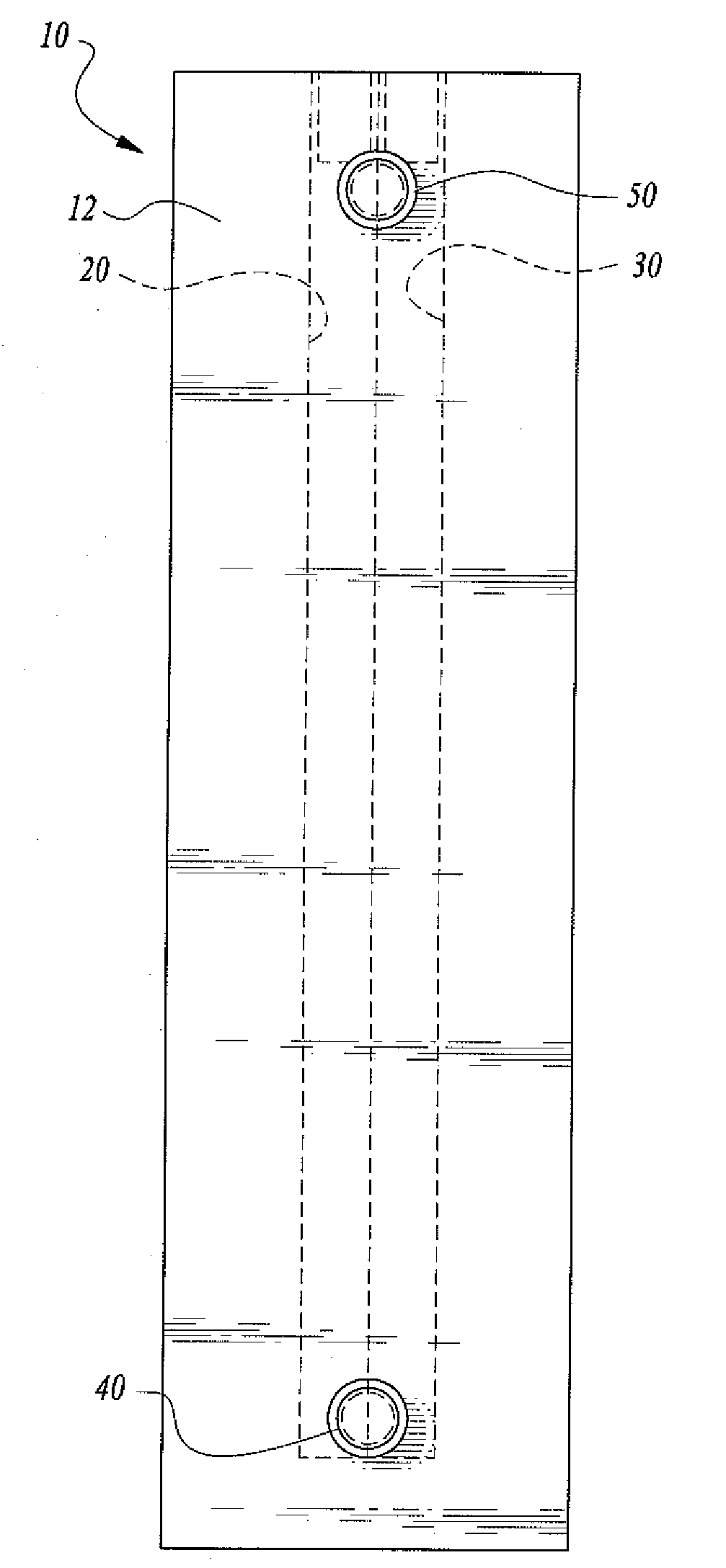
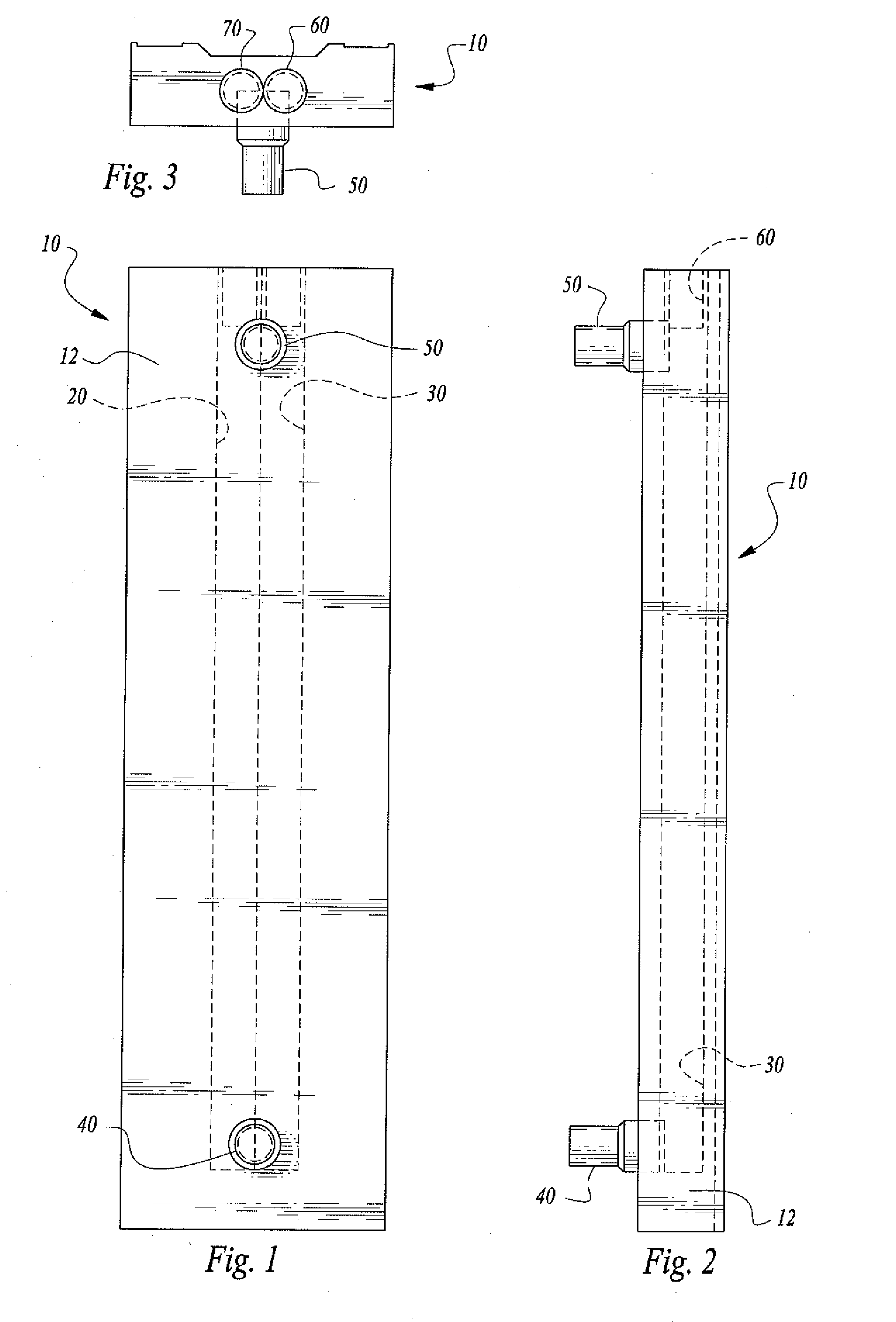
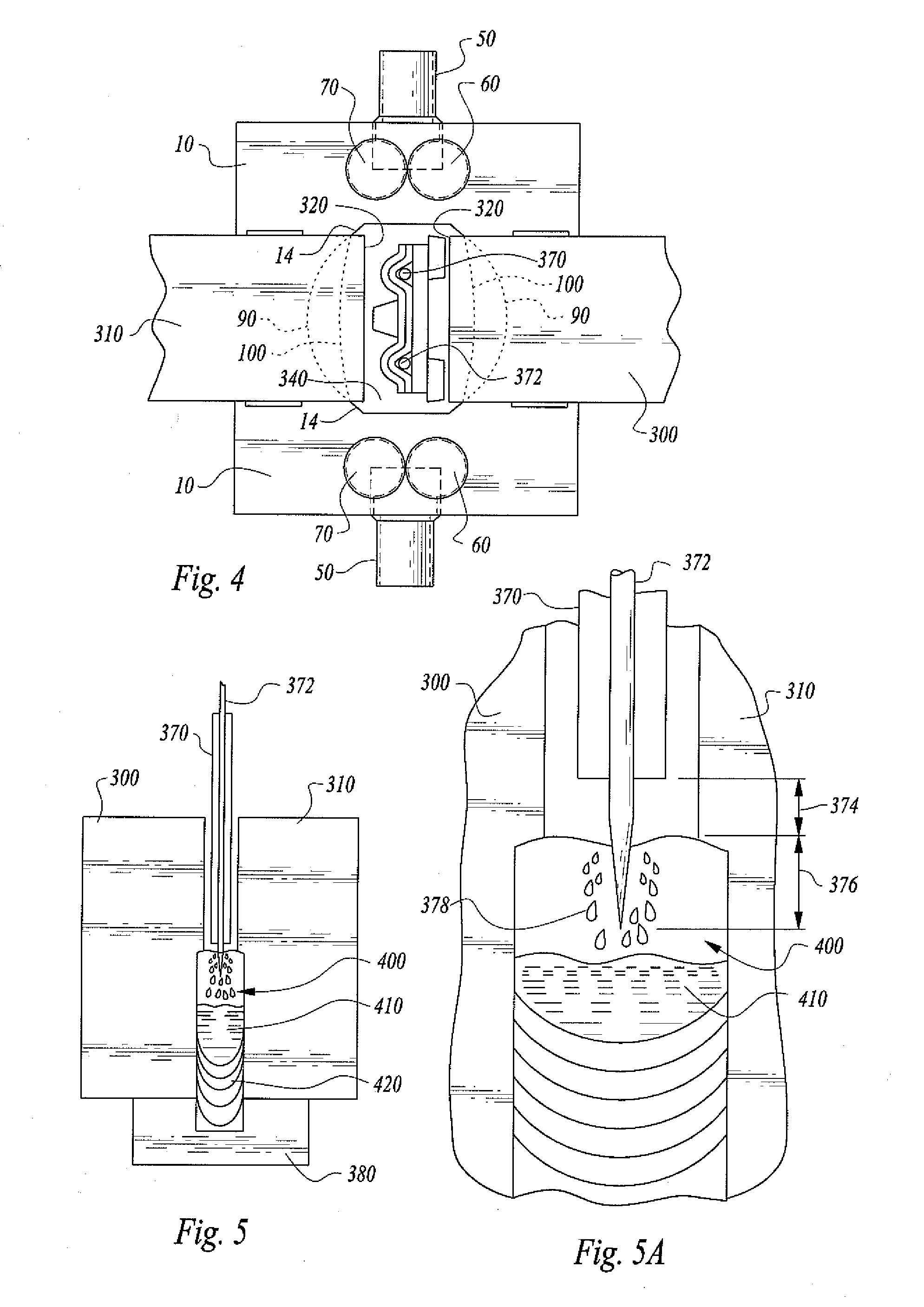
[0036]Referring more specifically to the drawings, for illustrative purposes the apparatus for air-cooled copper shoes for application with Electroslag welding systems and methods including, but not limited to, the “Air-Cooled VertaSlag Butt Welding Shoe,™” is embodied generally in FIG. 1-17. It will be appreciated that the system may vary as to configuration and as to the details of the parts, and that the method of using the system may vary as to details and to the order of steps, without departing from the basic concepts as disclosed herein. The apparatus for air-cooled copper shoes for application in Electroslag welding systems and methods is disclosed generally in terms of welding vertical columns, as this particular type of welding operation is widely used. However, the disclosed apparatus for air-cooled copper shoes may be used in a large variety of Electroslag and or Electrogas welding applications, as will be readily apparent to those skilled in the art.

[0037]Referring now ...


PUM

PropertyMeasurementUnit
Temperatureaaaaaaaaaa
Timeaaaaaaaaaa

Abstract

Adjustable articulated air-cooled copper welding shoes, capable of being controlled between 800 to 1000 degrees Fahrenheit during Electroslag welding operations, result in faster welds, smaller heat affected zone in the workpieces welded, and less base metal dilution. The shoes thus provide a smaller weld grain structure and stronger bonds in the weld fusion zone.

Description

CROSS-REFERENCES TO RELATED APPLICATIONS[0001]This U.S. non-provisional patent application is based upon and claims the filing date of U.S. provisional patent application Ser. No. 61 / 058,464 filed Jun. 3, 2008.STATEMENT REGARDING FEDERALLY SPONSORED RESEARCH OR DEVELOPMENT[0002]None.REFERENCE TO A MICRO-FICHE APPENDIX[0003]None.TECHNICAL FIELD[0004]This invention relates to welding. More particularly, the invention is related to air-cooled copper shoes for use in welding, particularly for Electroslag welding applications including, but not limited to, Arcmatic™ VertaSlag™ welding applications.BACKGROUND OF THE INVENTION[0005]Water-cooled copper welding shoes presently used for Electroslag welding applications keep the molten weld metal and flux bath contained in the weld cavity. Water circulates through the copper shoes at a flow rate of approximately 2 gallons per minute. This flow rate is sufficient to keep the copper shoes from melting from excessive heat. In consumable-guide Ele...

Claims


Application Information

Patent Timeline
03 Dec 2009
Publication
US20090294407A1
IPC
B23K25/00
CPC
B23K25/00
Inventors
BONG, WILLIAM L.