Air-cooled copper shoes for electroslag welding applications

a technology electroslag, which is applied in the field of air-cooled copper shoes, can solve the problems of high voltage levels, difficult to melt the edges of the parent material closest to the water-cooled shoes, and difficult to melt the parent material at the edge of the water-cooled shoe, so as to achieve excellent wetting, reduce the effect of voltage and increase the speed of weld travel

Inactive Publication Date: 2009-12-03
BONG WILLIAM L
View PDF5 Cites 4 Cited by
  • Summary
  • Abstract
  • Description
  • Claims
  • Application Information

AI Technical Summary

Benefits of technology

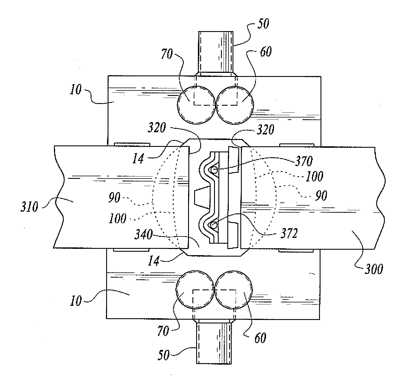
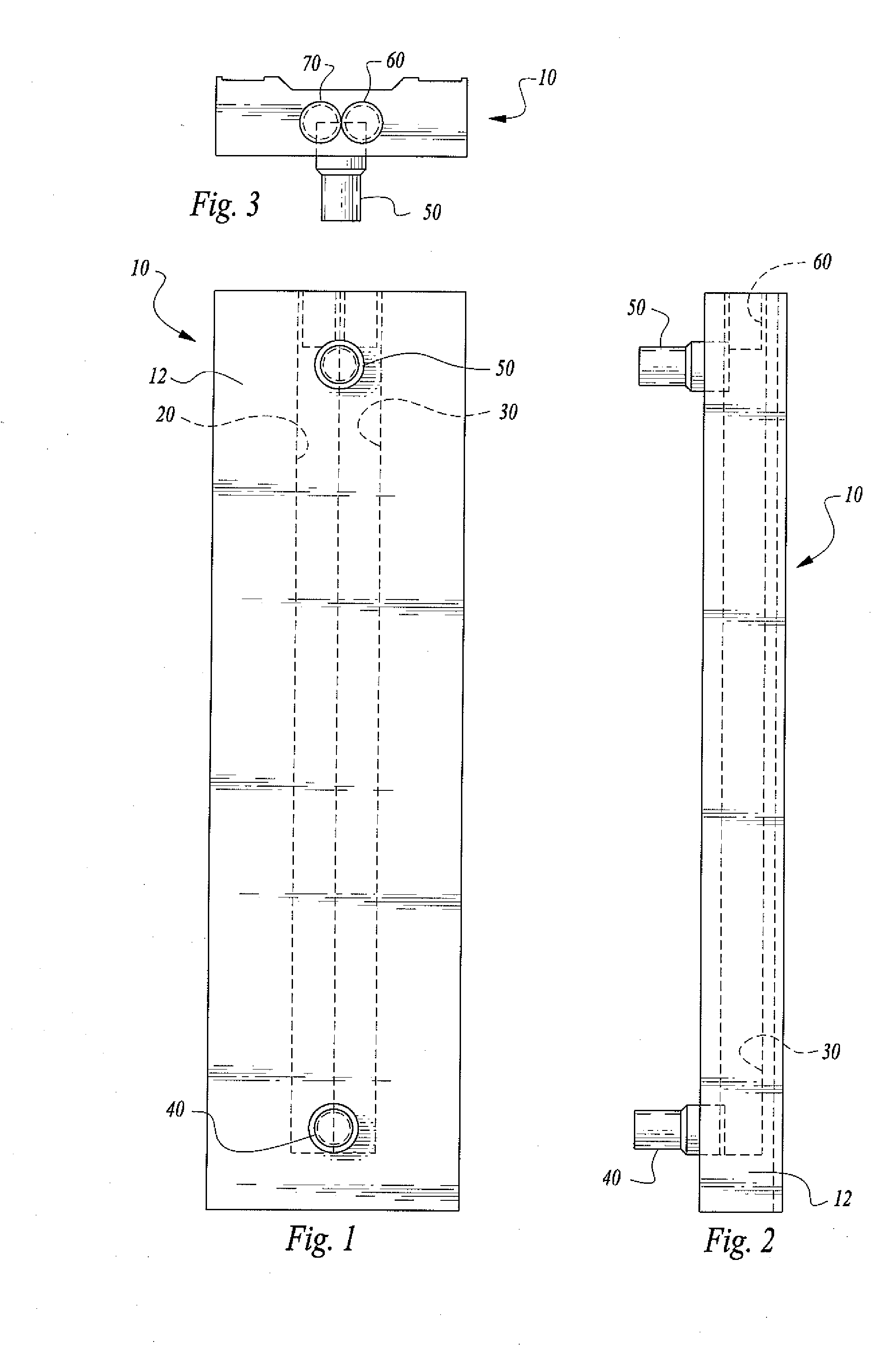
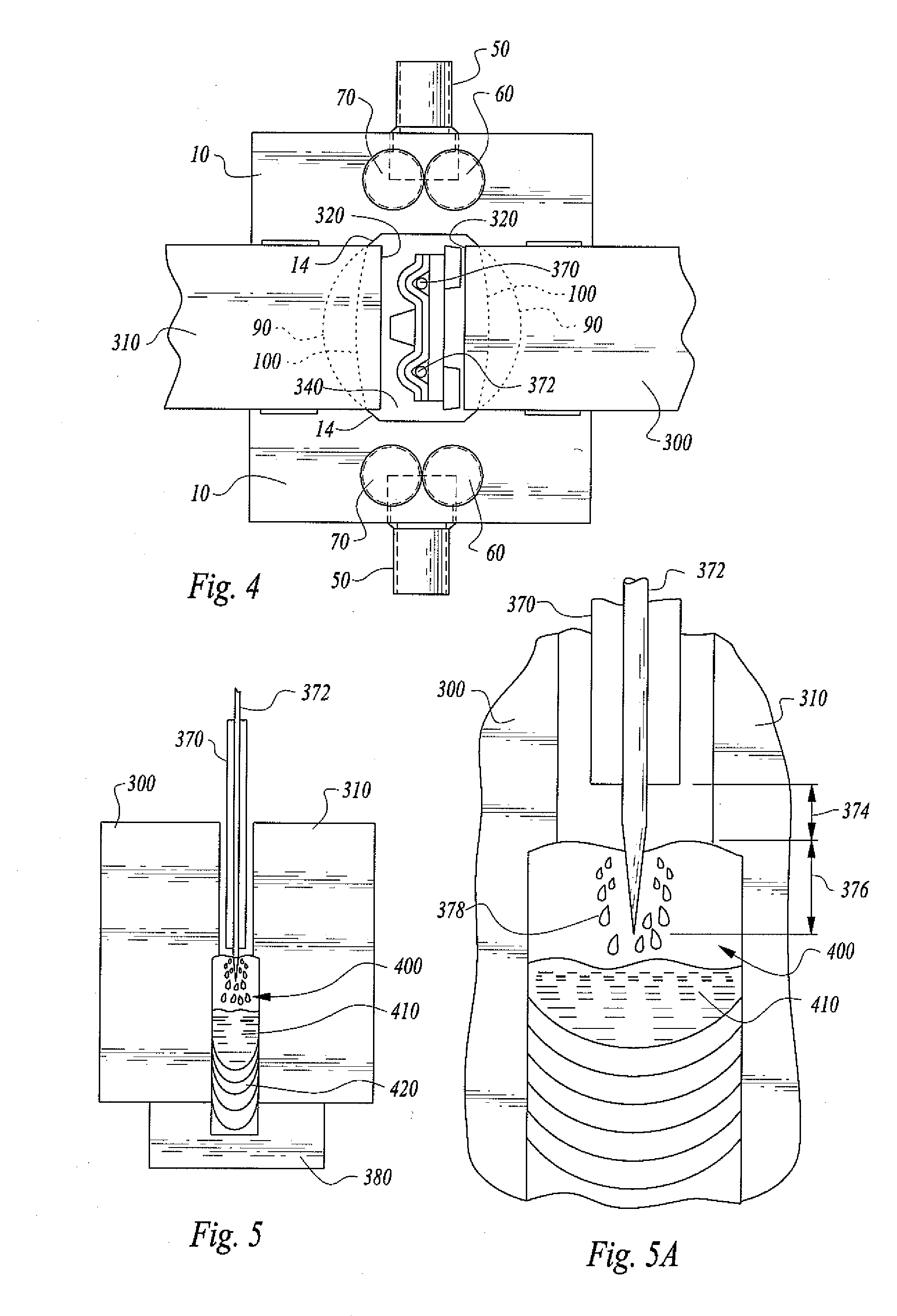
[0018]The new Arcmatic™“Air-Cooled VertaSlag™ Butt Welding Shoe™”, using air to cool the shoe (instead of water), allows the copper shoe to heat up to a temperature range of between 800 degrees Fahrenheit to 1000 degrees Fahrenheit. This is possible because the shoe, fittings and plugs are all fusion welded with electron beam fusion welds. If silver solder was used, the solder would melt at a temperature of 1200 degrees Fahrenheit; the fusion weld can heat up to the melting point of copper (approximately 1900 degrees Fahrenheit). If the copper shoes are at a temperature range of between 800 degrees Fahrenheit to 1000 degrees Fahrenheit during the Electroslag welding operation, the voltage can be substantially lowered and still attain excellent wetting on the edges of the parent material in the weld cavity. This allows the previously mentioned weld to be made at 1000-Amps and 28-Volts (instead of 38-Volts). Another factor that affects the total heat input into the weld is that the high temperature of the air-cooled copper shoe, allows the weld travel speed to be substantially increased. If the travel speed is doubled (say to 4 in/min VRR), the total wattage into the weld would then equal 7 kilowatts (1000×28/4=7-KW) instead of the 32 kilowatts required when welding with water-cooled copper shoes—only 22% of the heat input required by water-cooled shoes.
[0019]This massive heat reduction will result in the ability of welding faster, with a smaller HAZ and far less base metal dilution. The base metal d

Problems solved by technology

The problem with this excessive cooling of the base material on either side of the Electroslag weld joint also over chills the temperature of the weld puddle.
This over chilling of the weld puddle makes it very difficu

Method used


Image

  • Air-cooled copper shoes for electroslag welding applications
  • Air-cooled copper shoes for electroslag welding applications
  • Air-cooled copper shoes for electroslag welding applications

Examples


Embodiment Construction

[0033]One or more specific embodiments of the air-cooled copper shoes for use in welding, particularly for Electroslag welding applications will be described below. In an effort to provide a concise description of these embodiments, not all features of an actual implementation are described in the specification. It should be appreciated that in the development of any such actual implementation, as in any engineering or design project, numerous implementation-specific decisions must be made to achieve the developer's specific goals, such as compliance with system-related and business-related constraints, which may vary from one implementation to another. Moreover, it should be appreciated that such a development effort might be complex and time consuming, but would nevertheless be a routine undertaking of design, fabrication, and manufacture for those of ordinary skill having the benefit of this disclosure.

[0034]My following U.S. Letters Patent are incorporated by reference as if ful...


PUM

PropertyMeasurementUnit
Temperatureaaaaaaaaaa

Abstract

Opposing, paired and positionally adjustable air cooled welding shoes, run-off tabs, and sumps affixed at the junction of workpieces to be welded with an Electroslag welding system. The air-cooled shoes are capable of being controlled between 800 to 1000 degrees Fahrenheit, resulting in faster welds, smaller heat affected zone in the workpieces welded, and far less base metal dilution. These significant results provide a smaller weld grain structure and much stronger bond in the weld fusion zone.

Description

CROSS-REFERENCES TO RELATED APPLICATIONS[0001]This United States non-provisional patent application is based upon and claims the filing date of U.S. provisional patent application Ser. No. 61 / 058,464 filed Jun. 3, 2008.STATEMENT REGARDING FEDERALLY SPONSORED RESEARCH OR DEVELOPMENT[0002]None.REFERENCE TO A MICRO-FICHE APPENDIX[0003]None.TECHNICAL FIELD[0004]This invention relates to welding. More particularly, the invention is related to air-cooled copper shoes for use in welding, particularly for Electroslag welding applications.BACKGROUND OF THE INVENTION[0005]Water-cooled copper welding shoes presently used for Electroslag welding applications keep the molten weld metal and flux bath contained in the weld cavity. Water circulates through the copper shoes at a flow rate of approximately 2 gallons per minute. This flow rate is sufficient to keep the copper shoes from melting from excessive heat. In consumable-guide Electroslag welding, the shoes do not move. For longer joints the s...

Claims


Application Information

Patent Timeline
IPC IPC(8): B23K25/00
CPCB23K25/00
Inventor BONG, WILLIAM L.
Owner BONG WILLIAM L
Why Eureka
Try Eureka