
Voltage regulator attach for high current chip applications

a voltage regulator and high current chip technology, applied in the field of electronic systems, can solve the problems of not being suitable for soldering to a pcb, dc-dc has a significantly greater thermal mass, etc., and achieve the effect of small thermal mass and greater thermal mass

Active Publication Date: 2009-12-03
ORACLE INT CORP
View PDF44 Cites 55 Cited by
  • Summary
  • Abstract
  • Description
  • Claims
  • Application Information

AI Technical Summary

Benefits of technology

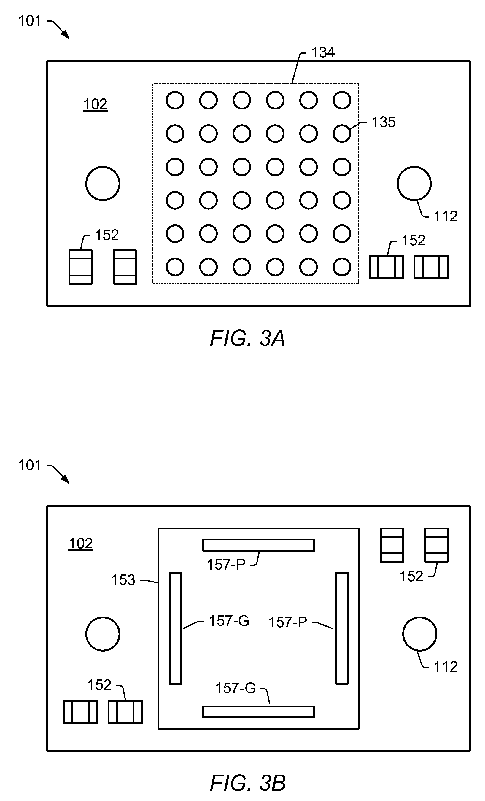
[0006]A voltage regulator is disclosed. In one embodiment, the voltage regulator includes an interposer having, on a first side, a plurality of electrical connections suitable for coupling to a printed circuit board (PCB). The interposer also includes at least one power plane and at least one ground plane, wherein each of the power and ground planes is coupled to one or more of the electrical connections. The voltage regulator further includes a DC-DC converter that is electro-mechanically attachable to and detachable from the interposer. The interposer includes a socket, on a second side, that is suitable to receive two or more electromechanical connecting members of the DC-DC converter. When the DC-DC converter is attached to the interposer, at least one of the electro-mechanical connecting members is electrically coupled to a power plane of the interposer, while at least one other of the electromechanical connecting members is electrically coupled to the ground plane.
[0007]An electronic assembly is also disclosed. In one embodiment, the electronic assembly includes a PCB and an IC package mounted to a first footprint on a first side of the PCB. A voltage regulator is mounted to a second side of the PCB, and is configured to provide power to an IC in the IC package. The voltage regulator includes an interposer having a plurality of electrical connections mounted to a footprint on the second side of the PCB and opposite the IC package. The interposer also includes a power plane and a ground plane. The power plane is electrically coupled to at least one of the electrical connections, while the ground plane is coupled to at least one other of the plurality of electrical connections. The voltage regulator further includes a DC-DC converter that is electro-mechanically coupled to the interposer. The DC-DC converter is electro-mechanically attachable to and detachable from the interposer. The interposer includes a socket configured to receive two or more electromechanical connecting members from the DC-DC converter. One of the electromechanical connecting members is electrically coupled to the power plane, while another one of the electromechanical connecting members is coupled to the ground plane.
[0008]A method for assembling an electronic assembly according to the disclosure herein includes soldering an IC package to a first side of a PCB, and coupling a voltage regulator to a second side of the PCB. Coupling the voltage regulator includes soldering an interposer to the second side of the PCB in a location opposite of the IC package. Coupling the voltage regulator further includes coupling a DC-DC converter to the interposer, wherein the interposer includes a socket configured to receive two or more electromechanical connecting members of the DC-DC converter, and wherein the DC-DC converter is electro-mechanically attachable to and detachable from the interposer. The operations of soldering the IC package and soldering the interposer are each performed prior to said coupling the DC-DC converter.
[0009]Accordingly, the method and apparatus disclosed herein enables a high-current voltage regulator to be attached to a PCB in order to distribute power to an IC mounted on the opposite side of the PCB. The method and apparatus split the voltage regulator into two different units, the interposer and the DC-DC converter. The interposer has a small thermal mass, and is thus suitable for soldering to the PCB. The DC-DC has a significantly greater thermal mass (due to the high current requirements), and is thus not suitable for soldering to a PCB. Instead, the DC-DC converter is electro-mechanically attached to the interposer via a socket in a manner that does not include soldering subsequent to soldering the interposer to the PCB. The DC-DC converter may be coupled to the interposer by bolts, pin-and-socket connector, surface-to-surface mating pints (e.g., a compression mounted land grid array), a flexible PCB portion that could be built as part of the DC-DC converter PCB (a ‘rigid-flex’ solution), or a cable-to-board connection.

Problems solved by technology

The DC-DC has a significantly greater thermal mass (due to the high current requirements), and is thus not suitable for soldering to a PCB.

Method used


Image

  • Voltage regulator attach for high current chip applications
  • Voltage regulator attach for high current chip applications
  • Voltage regulator attach for high current chip applications

Examples


Embodiment Construction

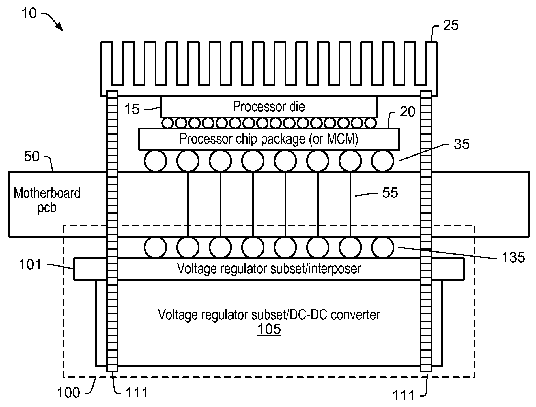
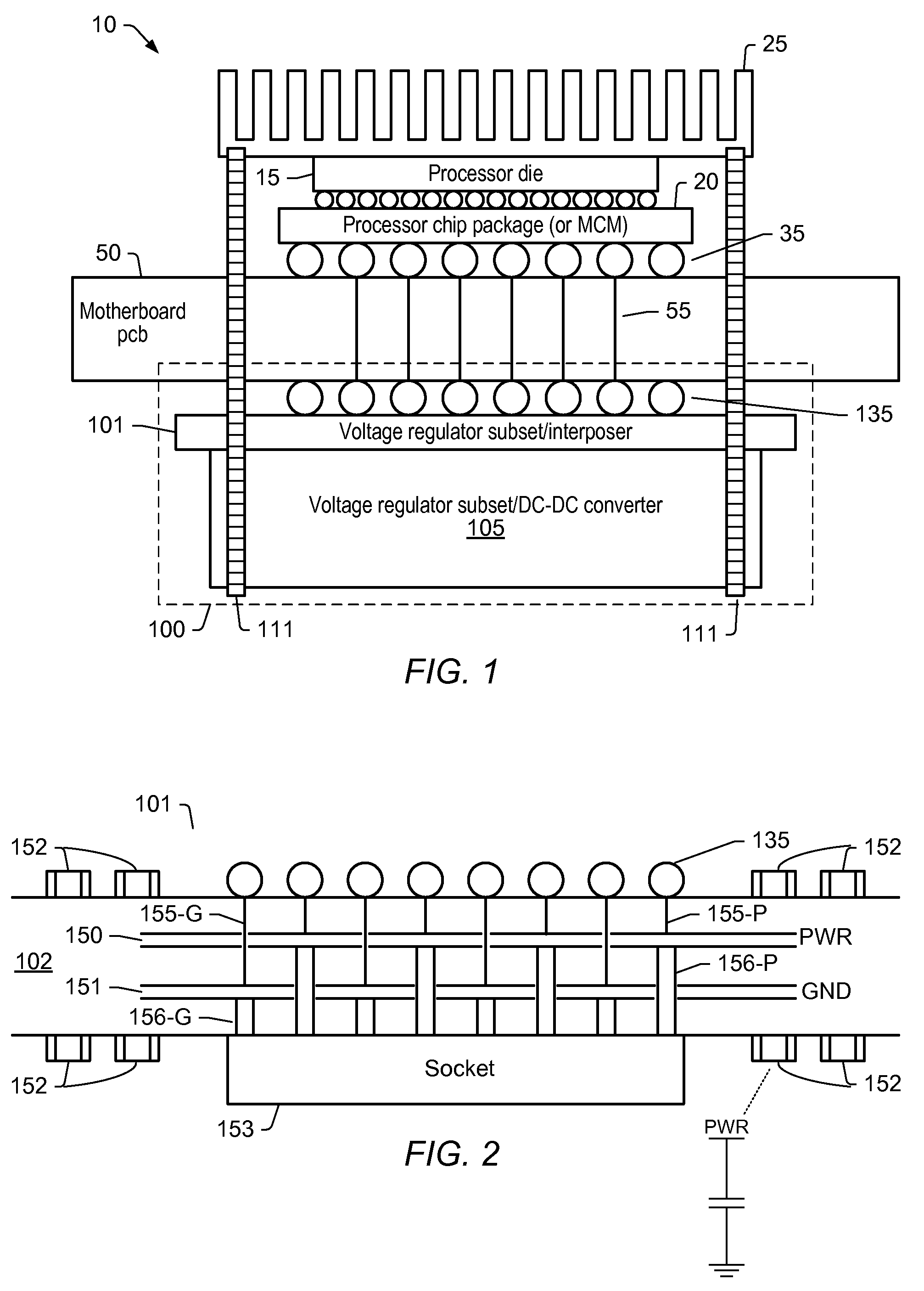
[0018]FIG. 1 is a drawing of one embodiment of an electronic assembly having a two-piece voltage regulator. In the embodiment shown, electronic assembly 10 includes a motherboard PCB (printed circuit board) 50 with a processor chip package 20 mounted to a first side and a voltage regulator 100 mounted to a second side. Processor chip package 20 includes a processor die 15 mounted thereon. It should be noted that embodiments having multiple chips coupled to processor chip package 20 are possible and contemplated, and as such, processor chip package 20 may be a multi-chip module (MCM). In this particular embodiment, a heat sink 25 is coupled to processor die 15 in order to disburse heat during operation.

[0019]Processor chip package 20 is coupled to motherboard 50 via a plurality of solder balls 35 arranged to form a ball-grid array (BGA). Embodiments utilizing pads forming a land-grid array (LGA) are also possible and contemplated (e.g., elastomeric connections, solder bumps, etc.). I...


PUM

PropertyMeasurementUnit
currentaaaaaaaaaa
thermal massaaaaaaaaaa
poweraaaaaaaaaa

Abstract

A voltage regulator. The voltage regulator includes an interposer having, on a first side, a plurality of electrical connections suitable for coupling to a printed circuit board (PCB). The interposer also includes at least one power plane and at least one ground plane, wherein each of the power and ground planes is coupled to one or more of the electrical connections. The voltage regulator further includes a DC-DC converter that is electro-mechanically attachable to and detachable from the interposer. The interposer includes a socket, on a second side, that is suitable to receive two or more electro-mechanical connecting members of the DC-DC converter. When the DC-DC converter is attached to the interposer, at least one of the electromechanical connecting members is electrically coupled to a power plane of the interposer, while at least one other one of the electromechanical connecting members is electrically coupled to the ground plane.

Description

BACKGROUND OF THE INVENTION[0001]1. Field of the Invention[0002]This invention relates to electronic systems, and more particularly, power distribution in electronic systems.[0003]2. Description of the Related Art[0004]The increasing ability to provide integrate more circuits on an integrated circuit (IC) die has resulted in much great processing power for devices such as microprocessors, digital signal processors, and other types of IC's. The greater processing power requires, in turn, higher pin counts and greater power requirements. Since there is a trend towards lower voltages, the increased processing power results in higher current requirements.[0005]Many types of modern packaged integrated circuits, such as processors, ASIC's, multi-chip modules, and so forth, require large amounts of current into and out of their respective packages during operation. Current requirements of 200-300 amperes are not uncommon. These high current requirements can pose significant challenges in p...

Claims


Application Information

Patent Timeline
Patent Type & Authority Applications(United States)
IPC IPC(8): H05K7/10H05K7/00H05K3/34
CPCH05K1/0231H05K1/0262H05K1/141H05K3/301H05K3/3436Y10T29/49144H05K2201/10325H05K2201/10409H05K2201/10545H05K2201/10598H05K2201/10734H05K7/1061H01L2224/16225H01L2224/73253H01L2924/15311
Inventor DOBLAR, DREW G.CHAKRABARTI, PRABHANSUBUSHUE, MICHAEL J.
Owner ORACLE INT CORP
Learn More