
Absorbable / biodegradable tubular stent and methods of making the same

a tubular stent, biodegradable technology, applied in the direction of prosthesis, antibacterial agents, blood vessels, etc., can solve the problems of increasing the risk of rupture, stent migration, stenosis, thrombosis, and other adverse medical effects, so as to prevent restenosis and infection.

Inactive Publication Date: 2009-12-03
POLY MED
View PDF26 Cites 10 Cited by
  • Summary
  • Abstract
  • Description
  • Claims
  • Application Information

AI Technical Summary

Benefits of technology

[0027]For many applications it is preferred that the stent contains at least one bioactive agent for preventing restenosis and infection. For some applications it is preferred that the stent contains at least 10 percent by weight of an inorganic radiopacifier.

Problems solved by technology

First, there are the self-expanding stents that typically are made of metal and that may include a biocompatible coating.
Self-expanding stents may be inappropriately sized for the sites where they are to be deployed, increasing the risk of rupture, stent migration, stenosis, and thrombosis as the stent continually tries to expand after deployment to its predetermined, optimal diameter.
Conversely, a stent sized too small for the lumen may project into the lumen, thereby causing a primary or secondary obstruction or migration.
Both self-expanding and expandable stents that are know in the art, because they are designed for permanent implantation in the body, increase the risk of restenosis, thrombosis, or other adverse medical effects because of the risk of adverse reaction by surrounding tissue, adverse reaction by the material flowing through the body lumen (such as blood or blood products), and deterioration of surrounding tissue and / or the stent itself.
Thus, these stents do not permit temporary placement within the body unless patient and surgeon are prepared to undertake a second procedure to remove the stent, which is difficult or impossible in most cases.
However, vascular smooth muscle cell migration and proliferation may be undesirable when it is uncontrolled (as in intimal hyperplasia) and results in the occlusion of the lumen that has been surgically opened by placement of the stent.
Thus, stents such as that described by Palmaz may be undesirable when the risk of intimal hyperplasia is substantial.
The benefits of a balloon-deployed stent, therefore, may not be realized in such circumstances.
Still another disadvantage of existing stents is that the materials from which they are made are rigid, and therefore, the compliance of the stents (i.e., the ability to control the flexibility of the material used to design stents for particular applications) is limited.
This has the disadvantage of exposing patients to risks associated with the placement of a device that may exhibit a rigidity in excess of that needed for the particular application.
The amount of the drug that can be delivered, and the time over which it may be released, therefore, may be limited by the quality of coating employed.
), the ability to achieve controlled, improved strength characteristics using the stent described by Beck is limited.
This limits the ability of a stent made according to Beck et al. to resist radially compressive forces imparted by the lumen upon the stent without creeping or relaxing, introducing a substantial risk of occluding the lumen.
Alternatively, one might use massive structures made according to Beck et al. to keep the lumen open, but in so doing, the normal function of the lumen would be perturbed significantly, possibly creating regions where flow of body liquids through the lumen would be severely restricted or stagnate, so that clots may form in those regions.
Goldberg does not, however, disclose the use of an expandable stent, nor does Goldberg et al. provide any information regarding the design of the stent or its method of deployment within the body.
However, it is believed by the present inventor that (1) the temperature required for expansion is close to 55° C. and can damage the vital tissue; and (2) the mechanical stability of the expanded configuration would be far less than optimal as one recognizes the stress-relaxation of a device having such shape.

Method used


Image

  • Absorbable / biodegradable tubular stent and methods of making the same
  • Absorbable / biodegradable tubular stent and methods of making the same
  • Absorbable / biodegradable tubular stent and methods of making the same

Examples


example 1

Synthesis and Characterization of Polyaxial Glycolide / ε-Caprolactone Segmented / Block Copolymers Exhibiting Two Extreme Melting Temperatures—General Method

[0062]The synthesis entails two steps. In the first step, a polyaxial polycaprolactone was prepared using trimethylolpropane as the initiator, at a monomer / initiator ratio of 500:1 to 700:1, depending on the sought molecular weight of the final polymer, in the presence of stannous octanoate as a catalyst, at a monomer / catalyst molar ratio of 20,000:1 to 30,000:1, depending on the final copolymer composition. Polymerization was conducted in a mechanically stirred, stainless steel reactor under a dry nitrogen atmosphere at 180° C. for 1.5 to 3 hours or until practically a complete conversion is achieved. This was determined by in-process monitoring of conversion using gel permeation chromatography (GPC). The polymer melt was allowed to cool slightly below 180° C. prior to adding a predetermined amount of glycolide in the second step ...

example 2

Preparation and Characterization of Typical Polyaxial Segmented Copolymer of ε-Caprolactone and Glycolide

[0063]Using the general method described in Example 1, typical copolymers, Co-P1 and Co-P3, were prepared and characterized. Key properties of these copolymers are summarized in Table I.

TABLE IAnalytical Data of Co-P1 to Co-P3 Tested as GroundSpecimens and Their Respective PrepolymersPropertiesCo-P1Co-P2Co-P3Weight Average Molecular Weight of475156Polycaprolactone Prepolymer, kDaCopolymer Composition: Glycolide to60:4060:4060:40Caprolactone Molar RatioCopolymer Inherent Viscosity, dL / g1.71.82InsolubleThermal Properties:Polycaprolactone Polyaxial PrepolymerTm, ° C.585756ΔHf, J / g708994Final Polyaxial CopolymeraTm1, ° C.424141ΔHf1, J / g181819Tm2, ° C.221222221ΔHf2, J / g828077aTm1 and ΔHf1 = Tm and ΔH of polycaprolactone block / segment.Tm2 and ΔHf2 = Tm and ΔH of polyglycolide block / segment.

example 3

Characterization of Thermally and Mechanically Treated Polyaxial Copolymer, Co-P2

[0064]Co-P2 was subjected to thermal and mechanical treatments similar to those expected to be encountered in key typical processes of those associated with stent fabrication and deployment at the desired biological site. Thin polymer films (0.2 mm) were compression molded at about 235° C. under a dry nitrogen atmosphere to provide test specimens for studying the effects of thermal and mechanical treatment (starting with the annealed, ground polymer and unannealed, unoriented films) on melting temperature (Tm) and heat of fusion (ΔHf) of the polycaprolactone and polyglycolide constituent blocks / segments of the polyaxial copolymer.

[0065]The specimens were used to determine changes in Tm and ΔHf as a result of annealing and / or uniaxial orientation in tensile mode. Summary of the experimental data are depicted in Table II. The sets of experiments noted in Table II were designed to determine the effects of ...


PUM

PropertyMeasurementUnit
temperatureaaaaaaaaaa
Tmaaaaaaaaaa

Abstract

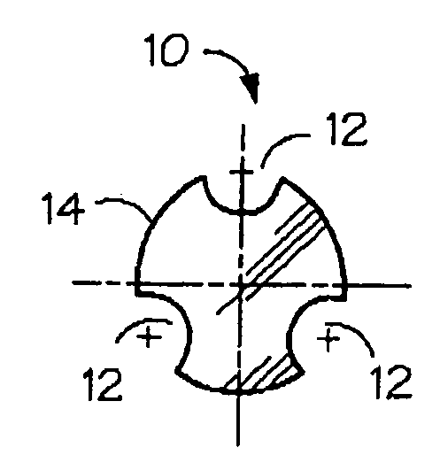
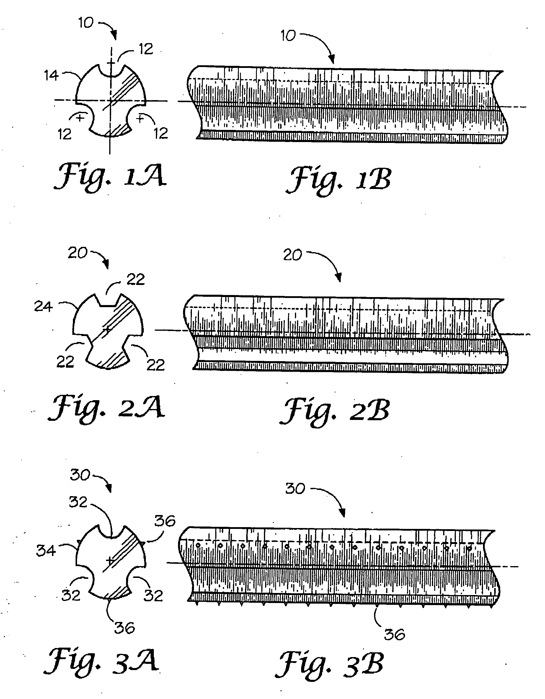
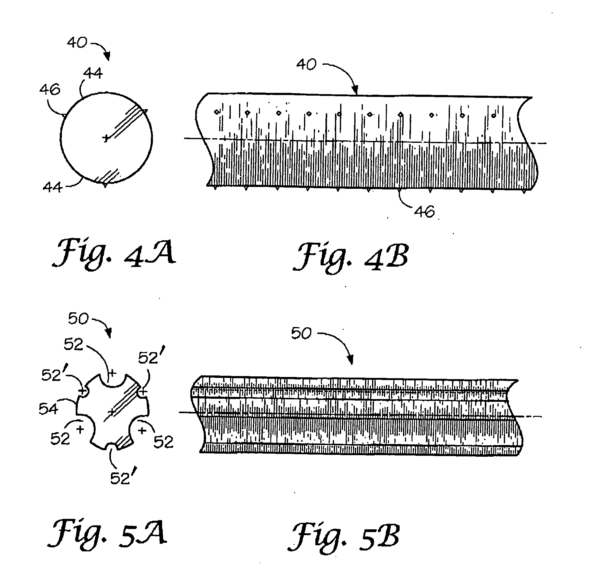
Medicated or unmedicated, absorbable / biodegradable, polymeric tubular stents for temporary placement in body lumens maintain patency and provide dimensional stability at the biological site. The stent design is based on a radially fluted, tubular form having grooves or flutes along its entire length for expansion to a predetermined diameter after deployment, using a balloon catheter, into a tubular body lumen through outward deformation of the fluted wall.

Description

[0001]The present is a divisional application of U.S. Ser. No. 10 / 768,834, filed Jan. 31, 2004, which claimed the benefit of prior provisional application, U.S. Ser. No. 60 / 444,023, filed Jan. 31, 2003.FIELD OF THE INVENTION[0002]This invention relates to an absorbable / biodegradable, radially fluted, tubular stent having grooves or flutes along its entire length for expansion to a predetermined range of diameters, depending on the number and variability in the shape and depth of the flutes or grooves, after deployment, using a balloon-catheter, in a tubular body lumen through outward deformation of said grooves to yield an essentially circular cross-section to stabilize the internal dimensions of the treated conduit or lumen as in the case of an endovascular stent that is used in preventing vascular restenosis.BACKGROUND OF THE INVENTION[0003]Stents, including cardiovascular and biliary stents, are well known as devices that are used to support a body lumen, such as an artery, vein,...

Claims


Application Information

Patent Timeline
Patent Type & Authority Applications(United States)
IPC IPC(8): A61F2/06A61FA61F2/02A61F2/86A61L27/20A61L27/34A61L27/58A61L31/06A61L31/14
CPCA61F2/86A61F2210/0004A61L31/06A61F2230/006A61L31/148A61F2220/0016C08L67/04A61P31/04
Inventor SHALABY, SHALABY W.
Owner POLY MED
Learn More