Method for removing micro-debris and device of the same

a technology of micro-debris and a device, applied in the direction of sonic/ultrasonic/infrasonic transmission, manufacturing tools, chemistry apparatus and processes, etc., can solve the problems of increasing surface roughness, affecting proper laser performance, and machining precision decreasing, so as to improve machining precision and facilitate operation. , the effect of reducing the machining precision

Inactive Publication Date: 2009-12-10
IND TECH RES INST
View PDF21 Cites 2 Cited by
  • Summary
  • Abstract
  • Description
  • Claims
  • Application Information

AI Technical Summary

Benefits of technology

[0026]The micro-debris removal method and device of the present invention are characterized by designing standing waves to be capable of extending across the entire machining surface, and then moving and concentrating the micro-debris by the standing waves to standing wave nodes located outside the machining range, subsequently removing the micro-debris from the standing wave nodes, thereby effectively removing the micro-debris away from the machining range, and comparatively solving drawbacks of prior art. Air flow can be used to remove the micro-debris. In addition, after concentrating the micro-debris at the standing wave nodes, at any stage of the machining process, after, during, or when the acoustic wave generator is stopped, the micro-debris can be removed by air suction, dropping off due to gravity of the micro-debris, or gravity guiding etc. Accordingly, the present invention is capable of not only preventing drawbacks of prior art, wherein micro-debris is deposited at the machining location and thus decreasing machining precision, but also comparatively enhancing the machining precision, providing easy operation, and accommodating to various laser machining technologies that may involve movement of the machining platform and the laser source.

Problems solved by technology

However, in a process of laser micromachining performed on machined object, ablated micro-debris will scatter all over the surroundings of the machined object, and the micro-debris will even accumulate on the machined object if not removed instantly, subsequently decreasing machining precision and increase surface roughness.
In addition, said technology can further dispose an air pressure channel inside the nozzle for forming an air flow circuit, thereby preventing the micro-debris from attaching onto the laser channel above the machined object and affecting proper laser performance.
However, when using air flow to remove micro-debris, air blowing nozzle or air suction nozzle should be disposed properly and also air flow direction has to be well controlled, but the air blowing nozzle or air suction nozzle cannot be adjusted easily since it is disposed closely to the laser beam, thereby causing micro-debris to be removed incompletely or flow to improper location.
Meanwhile, temperature is one of important parameters in laser machining, while removing micro-debris by means of air blowing, air suction, or both, turbulent flow will cause uneven temperature in neighboring areas of the machining location, and when the temperature or temperature difference is too high, precision and quality of laser machining are decreased, or even worse, the process of micro-debris ablation cannot be performed normally.
In addition, said patent technology has to be disposed with air pressure source or negative pressure source for correspondingly supporting the air blowing nozzle or air gushing nozzle to remove micro-debris, which not only increases cost, but also occupies more space and causes more inconvenience during use.
Besides, said patent technology has to be operated in a vacuum environment, equipments necessary to implement this are usually very expensive.
As a result, if said patent technology is applied, location of the air blowing nozzle or air gushing nozzle should be changed correspondingly as well, thereby causing difficulty in removing micro-debris; in other words, said patent technology is not applicable to the laser direct writing technique.
However, said patent technology does not discuss how to remove micro-debris produced in a laser machining process.
Hence, it is a highly urgent issue in the industry to provide a method for removing micro-debris produced in laser machining processes and device of the same capable of effectively solving abovementioned drawbacks of the prior art.

Method used


Image

  • Method for removing micro-debris and device of the same
  • Method for removing micro-debris and device of the same
  • Method for removing micro-debris and device of the same

Examples


Embodiment Construction

[0030]The following illustrative embodiments are provided to illustrate the disclosure of the present invention, these and other advantages and effects can be apparently understood by those in the art after reading the disclosure of this specification. The present invention can also be performed or applied by other different embodiments. The details of the specification may be on the basis of different points and applications, and numerous modifications and variations can be devised without departing from the spirit of the present invention.

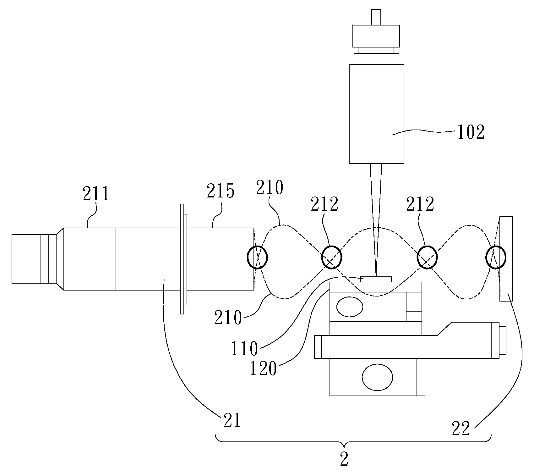
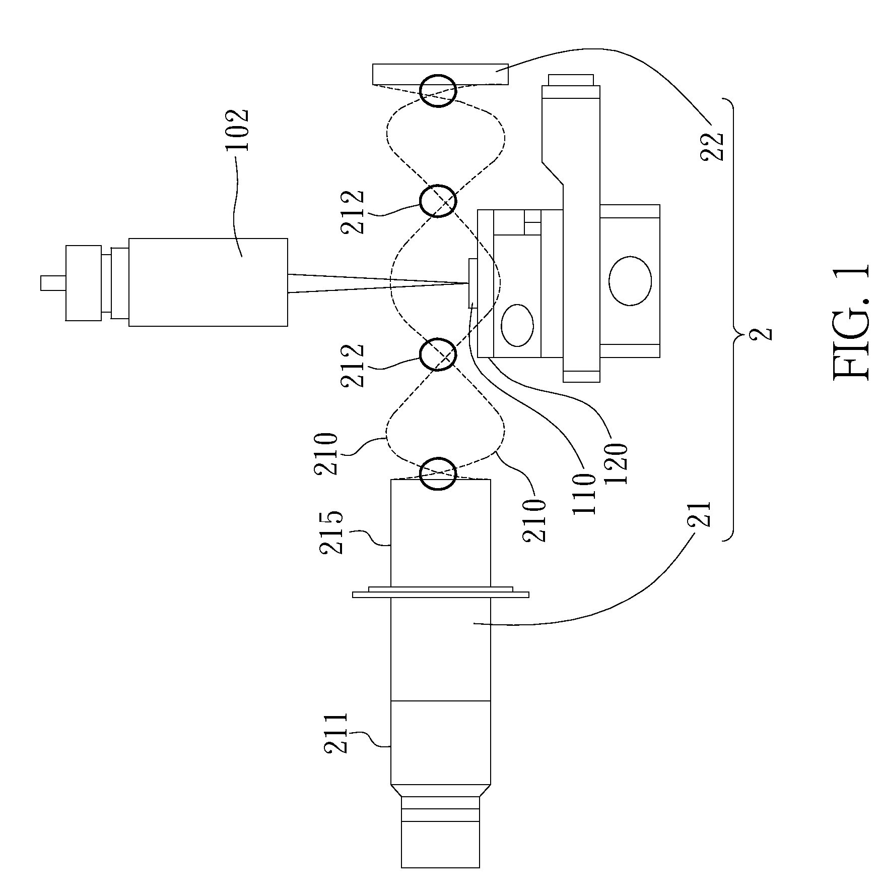
[0031]Please refer to FIG. 1, which is a diagram illustrating a first embodiment of method and device of the present invention for removing micro-debris; as shown in the FIG. the present invention is for removing micro-debris generated during a laser machining process performed on a machined object 110, the machined object 110 is placed on a movable machining platform 120 within a machining range, thereby performing machining on a machining locat...


PUM

PropertyMeasurementUnit
temperatureaaaaaaaaaa
particle diameteraaaaaaaaaa
frequencyaaaaaaaaaa

Abstract

The present invention provides a method for removing micro-debris generated in a laser machining process operated on machined object and device of the same. The machined object is placed on a movable machining platform within a machining range and machined at a particular machining location. By disposing an acoustic wave generator and a reflector part, or by disposing a plurality of acoustic wave generators, at least two standing waves extending across the machining range and two standing wave nodes are generated. The micro-debris generated from the laser machining process is moved away by the standing waves to concentrate at the standing wave nodes, and subsequently removed from the standing wave nodes.

Description

BACKGROUND OF THE INVENTION[0001]1. Field of the Invention[0002]This invention generally relates to a technique for removing micro-debris, and more specifically, to a method for removing micro-debris generated in laser machining processes performed on machined objects and device of the same.[0003]2. Description of Related Art[0004]Along with the development in semiconductor and microsystem technologies, developments of various electronic products are toward higher memory capacities and higher performances; therefore requirements of component parts of electronic products are toward higher precision and miniaturization. Prior semiconductor fabrication technique is integrated with photolithography and etching technologies for producing fine line structures and patterns; and since laser machining is capable of performing micro drilling, micro cutting, micro carving, micro machining, micro soldering, etc., laser machining has been commonly used to replace some of conventional semiconduct...

Claims


Application Information

Patent Timeline
Patent Type & Authority Applications(United States)
IPC IPC(8): H04B11/00
CPCB08B5/04B23K26/16B08B17/02B08B15/04
Inventor TSAI, WU-JUNGCHENG, CHUNG-WEITSAI, MI-CHINGYAO, WU-SUNGWANG, SHENG-HE
Owner IND TECH RES INST
Why Eureka
Try Eureka