Method and apparatus for power converter for class d audio power amplifiers

a power amplifier and power converter technology, applied in the direction of dc-dc conversion, dc-dc conversion, efficient power electronics conversion, etc., can solve the problems of large capacitance disproportionate to the lower power output large capacitance of 50,000 uf, and large capacitance of low power amplifiers driving low impedance loads. , to achieve the effect of minimizing the effects of off side charging and rail sag, good line regulation

Active Publication Date: 2009-12-17
RGB SYST INC
View PDF3 Cites 29 Cited by
  • Summary
  • Abstract
  • Description
  • Claims
  • Application Information

AI Technical Summary

Benefits of technology

[0022]A method and apparatus for power conversion in a class D amplifier is provided. The power conversion is achieved using synchronous rectifiers in a regulated half bridge power supply, taking the sum of the positive and negative rails as feedbac

Problems solved by technology

A class D audio power amplifier in half bridge configuration presents several problems for the power supply.
One example of such problems is off side charging.
Off side charging will cause the magnitude of the unloaded supply voltage of the unloaded rail to increase, which can easily make it exceed the voltage ratings of the class D amplifier devices, as well as causing distortion by introducing nonlinearity in the forward transfer function.
However, the capacitance required is not proportional to the power output of the amplifier, but rather inversely proportional to the load impedance.
This means that low power amplifiers driving low impedance loads require a large amount of capacitance disproportionate to their lower power output.
A total capacitance of 50,000 uF is very large and unrealistic for a low power design, as large value capacitors are typically expensive and of large physical size, which both run counter to the low cost and small size generally preferred in modern electronics.
The difficulty of providing power to a half bridge class D amplifier is further complicated by the use of a regulated power supply, which are typically regulated based only the positive supply voltage rail.
If the positive rail is loaded and the negati

Method used


Image

  • Method and apparatus for power converter for class d audio power amplifiers
  • Method and apparatus for power converter for class d audio power amplifiers
  • Method and apparatus for power converter for class d audio power amplifiers

Examples


Embodiment Construction

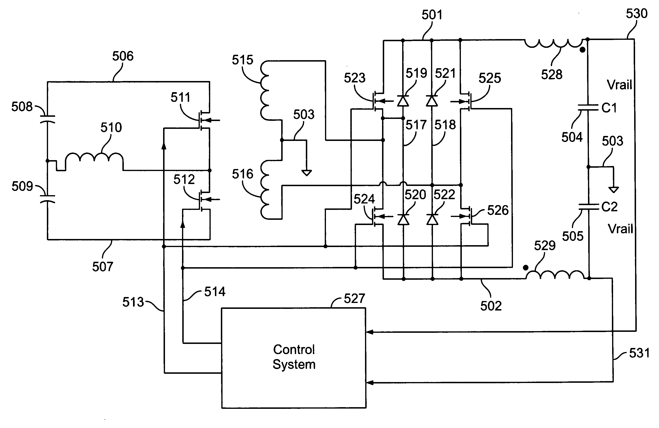
[0034]A method and apparatus for power conversion in a class D amplifier is provided. The power conversion is achieved using synchronous rectifiers in a regulated half bridge power supply, taking the sum of the positive and negative rails as feedback, in order facilitate energy transfer between positive and negative output rails. This minimizes the effects of off side charging and rail sag, as well as achieving good line regulation, while allowing use of very small, low value output capacitors.

[0035]FIG. 4 is a waveform diagram illustrating an example of power supply voltage rail regulation in accordance with at least one embodiment. Waveform 401 depicts an AC waveform at the output of a transformer secondary winding, before rectification. Waveform 402 depicts a positive power supply voltage rail substantially free of ripple arising from off side charging. Waveform 403 depicts a negative power supply voltage rail substantially free of ripple arising from off side charging. As can be...


PUM


Abstract

A method and apparatus for power conversion in a class D amplifier is provided. The power conversion is achieved using synchronous rectifiers in a regulated half bridge power supply, taking the sum of the positive and negative rails as feedback, in order facilitate energy transfer between positive and negative output rails. This minimizes the effects of off side charging and rail sag, as well as achieving good line regulation, while allowing use of very small, low value output capacitors.

Description

CROSS-REFERENCE TO RELATED APPLICATION[0001]This patent application claims the benefit of the filing date of U.S. Provisional Patent Application No. 61 / 061,986 filed Jun. 16, 2008.BACKGROUND OF THE INVENTION[0002](1) Field of the Invention[0003]The present invention relates generally to electronics for converting power and amplifying signals and more particularly to a method and apparatus for providing power to an amplifier.[0004](2) Description of the Related Art[0005]FIG. 1 is a schematic diagram illustrating an example of a half bridge class D amplifier. The half bridge class D amplifier comprises a positive supply voltage rail 101, a negative supply voltage rail 102, a ground 103, a positive supply voltage filter capacitor 104, a negative supply voltage filter capacitor 105, a high side driver 106, a low side driver 107, a low pass output filter inductor 108, a low pass output filter capacitor 109, and a load 110. A class D audio power amplifier in half bridge configuration pres...

Claims


Application Information

Patent Timeline
IPC IPC(8): H03F3/217H03F3/04
CPCH02M3/33592H03F3/217H03F3/2173H03F2200/03H03F2203/21193Y02B70/1475H02M5/4585H03F3/2171H03F2200/504Y02B70/10
Inventor MENDENHALL, ERIC
Owner RGB SYST INC
Why Eureka
Try Eureka